


Soil Moisture Controller Module Board Kit Automatic Watering Device Automatic Watering DIY Electronic Production Parts Diy Kit


Soil Moisture Controller Module Board Kit Automatic Watering Device Automatic Watering DIY Electronic Production Parts Diy Kit
brand: DIYTECH SKU:DT2075-03- guaranteeQuality checked
- Special gift cardsSpecial gift cards
- Free return Within 60 days
- Consultancyservice@diytech.cc
product manual:
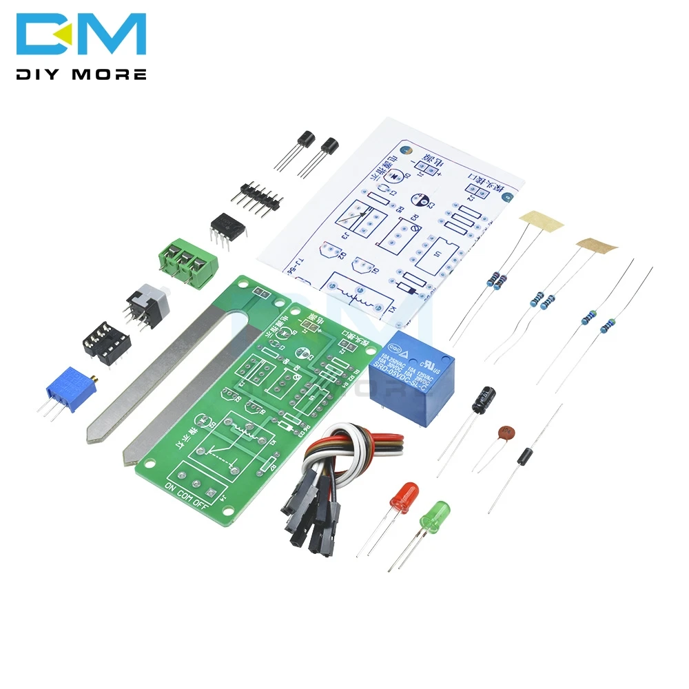
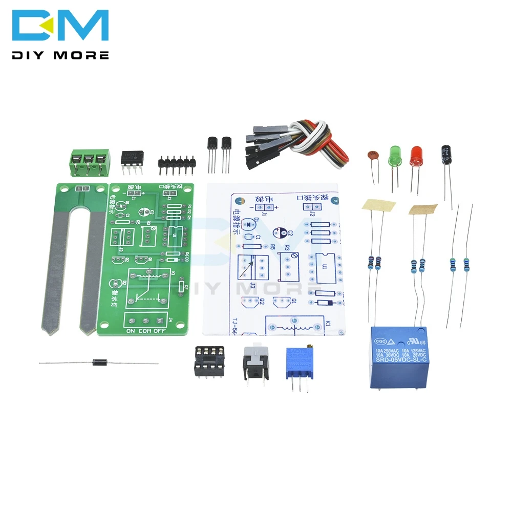
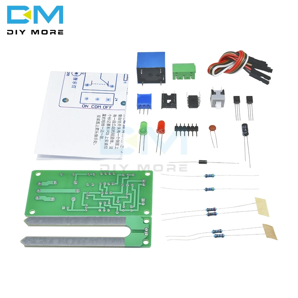
The soil moisture controller detects the soil moisture through the soil moisture sensor (fork-shaped circuit board). The soil moisture sensor is not conductive in the air. After inserting the soil, the more moisture in the soil, the resistance on the two terminals of the humidity sensor. The lower, the greater the resistance. The sensor's signal is connected to the control circuit through the J2 probe interface. The resistor R2 is connected in series on the humidity probe. The change in humidity is reflected as the change in the voltage at the inverting input of the voltage comparator U1A. If it is lower than the voltage at the same input terminal of U1A, the comparator outputs a high level, otherwise the output is low. Flat, capacitor C2 is a stable output signal to prevent the relay frequency from operating when the humidity is detected. The self-locking switch J3 is used to control the action mode of the relay (whether the high-level pull-in relay is outputted in the first leg of U1A or the low-level pull-in relay in the first leg of U1A). Pay attention to the direction when installing the self-locking switch. The self-locking switch has a raised short vertical line on one side that matches the short side of the mounting position on the PCB. Adjustable resistor R3 is used to adjust the humidity control value. The relay output terminal J4 can be used as an electrical switch for some high-power appliances, such as pumps, sprays and other machinery. Thereby achieving automatic control. Light-emitting diode D1 is the control board power supply indication, and D2 is the relay pull-in action indication. Transistor Q1 can be seen as a non-gate.
Working voltage: 5V DC voltage
Load: 250V 10A AC or 30V 10A DC (currents below this range can be used);


Other Customers also buy:
-

 $4.20{"id":4521872851031,"title":"Soil Moisture Controller Module Board Kit Automatic Watering Device Automatic Watering DIY Electronic Production Parts Diy Kit","handle":"soil-moisture-controller-module-board-kit-automatic-watering-device-automatic-watering-diy-electronic-production-parts-diy-kit","description":"\u003cwidget data-widget-type=\"customText\" id=\"33684419\" title=\"Head\" type=\"custom\"\u003e\u003c\/widget\u003e\n\u003cp\u003e\u003cbr\u003e\u003c\/p\u003e\n\u003cp\u003e\u003cspan\u003e\u003cspan\u003e\u003cspan style=\"font-size: 18px; font-family: trebuchet ms;\"\u003eproduct manual:\u003c\/span\u003e\u003cbr\u003e\u003cbr\u003e\u003c\/span\u003e\u003cspan style=\"font-size: 18px; font-family: trebuchet ms;\"\u003eThe soil moisture controller detects the soil moisture through the soil moisture sensor (fork-shaped circuit board). The soil moisture sensor is not conductive in the air. After inserting the soil, the more moisture in the soil, the resistance on the two terminals of the humidity sensor. \u003c\/span\u003e\u003cspan style=\"font-size: 18px; font-family: trebuchet ms;\"\u003eThe lower, the greater the resistance. \u003c\/span\u003e\u003cspan style=\"font-size: 18px; font-family: trebuchet ms;\"\u003eThe sensor's signal is connected to the control circuit through the J2 probe interface. \u003c\/span\u003e\u003cspan style=\"font-size: 18px; font-family: trebuchet ms;\"\u003eThe resistor R2 is connected in series on the humidity probe. The change in humidity is reflected as the change in the voltage at the inverting input of the voltage comparator U1A. If it is lower than the voltage at the same input terminal of U1A, the comparator outputs a high level, otherwise the output is low. \u003c\/span\u003e\u003cspan style=\"font-size: 18px; font-family: trebuchet ms;\"\u003eFlat, capacitor C2 is a stable output signal to prevent the relay frequency from operating when the humidity is detected. \u003c\/span\u003e\u003cspan style=\"font-size: 18px; font-family: trebuchet ms;\"\u003eThe self-locking switch J3 is used to control the action mode of the relay (whether the high-level pull-in relay is outputted in the first leg of U1A or the low-level pull-in relay in the first leg of U1A). Pay attention to the direction when installing the self-locking switch. \u003c\/span\u003e\u003cspan style=\"font-size: 18px; font-family: trebuchet ms;\"\u003eThe self-locking switch has a raised short vertical line on one side that matches the short side of the mounting position on the PCB. \u003c\/span\u003e\u003cspan style=\"font-size: 18px; font-family: trebuchet ms;\"\u003eAdjustable resistor R3 is used to adjust the humidity control value. \u003c\/span\u003e\u003cspan style=\"font-size: 18px; font-family: trebuchet ms;\"\u003eThe relay output terminal J4 can be used as an electrical switch for some high-power appliances, such as pumps, sprays and other machinery. \u003c\/span\u003e\u003cspan style=\"font-size: 18px; font-family: trebuchet ms;\"\u003eThereby achieving automatic control. \u003c\/span\u003e\u003cspan style=\"font-size: 18px; font-family: trebuchet ms;\"\u003eLight-emitting diode D1 is the control board power supply indication, and D2 is the relay pull-in action indication. \u003c\/span\u003e\u003cspan\u003e\u003cspan style=\"font-size: 18px; font-family: trebuchet ms;\"\u003eTransistor Q1 can be seen as a non-gate.\u003c\/span\u003e\u003cbr\u003e\u003c\/span\u003e\u003c\/span\u003e\u003c\/p\u003e\n\u003cp\u003e \u003c\/p\u003e\n\u003cspan\u003e\u003cspan\u003e\u003cspan\u003e\u003c\/span\u003e\u003cspan\u003e\u003cspan style=\"font-size: 18px; font-family: trebuchet ms;\"\u003eWorking voltage: 5V DC voltage\u003c\/span\u003e\u003cbr\u003e\u003cbr\u003e\u003c\/span\u003e\u003cspan style=\"font-size: 18px; font-family: trebuchet ms;\"\u003eLoad: 250V 10A AC or 30V 10A DC (currents below this range can be used);\u003c\/span\u003e\u003c\/span\u003e\u003c\/span\u003e\n\u003cp\u003e \u003c\/p\u003e\n\u003cp\u003e\u003cbr\u003e\u003c\/p\u003e\n\u003cp\u003e \u003c\/p\u003e\n\u003cp\u003e\u003cimg style=\"width: 1000px;\" src=\"http:\/\/ae01.alicdn.com\/kf\/He30ac5e629f54bfcbedeb7c996a60eca1.jpg\"\u003e\u003c\/p\u003e\n\u003cp\u003e\u003cimg style=\"width: 1000px;\" src=\"http:\/\/ae01.alicdn.com\/kf\/Hb57a3f4e9b304e0886c68a6e1d8e9bbb2.jpg\"\u003e\u003c\/p\u003e\n\u003cp\u003e\u003cimg style=\"width: 1000px;\" src=\"http:\/\/ae01.alicdn.com\/kf\/H3179619a6a874bffa1bd6d09ec09b714I.jpg\"\u003e\u003c\/p\u003e\n\u003cp\u003e\u003cimg style=\"width: 1000px;\" src=\"http:\/\/ae01.alicdn.com\/kf\/Hd815a8dae9f04cda90352a394f57913cH.jpg\"\u003e\u003c\/p\u003e\n\u003cp\u003e\u003cimg style=\"width: 1000px;\" src=\"http:\/\/ae01.alicdn.com\/kf\/H52381604fbfb4b88900e2ba5f5bec75a1.jpg\"\u003e\u003c\/p\u003e\n\u003cp\u003e\u003cimg style=\"width: 1000px;\" src=\"http:\/\/ae01.alicdn.com\/kf\/H8bfa68f56f0d448b84b9f19790b1a171s.jpg\"\u003e\u003c\/p\u003e","published_at":"2020-05-22T21:40:38+08:00","created_at":"2020-05-22T21:40:46+08:00","vendor":"DIYTECH","type":"Funny DIY","tags":["Kits","Relay","Relays"],"price":459,"price_min":459,"price_max":1349,"available":true,"price_varies":true,"compare_at_price":null,"compare_at_price_min":0,"compare_at_price_max":0,"compare_at_price_varies":false,"variants":[{"id":32154705625175,"title":"3pcs","option1":"3pcs","option2":null,"option3":null,"sku":"DT2075-03","requires_shipping":true,"taxable":false,"featured_image":null,"available":true,"name":"Soil Moisture Controller Module Board Kit Automatic Watering Device Automatic Watering DIY Electronic Production Parts Diy Kit - 3pcs","public_title":"3pcs","options":["3pcs"],"price":459,"weight":93,"compare_at_price":null,"inventory_management":null,"barcode":"","requires_selling_plan":false,"selling_plan_allocations":[]},{"id":32154705657943,"title":"10pcs","option1":"10pcs","option2":null,"option3":null,"sku":"DT2075-10","requires_shipping":true,"taxable":false,"featured_image":null,"available":true,"name":"Soil Moisture Controller Module Board Kit Automatic Watering Device Automatic Watering DIY Electronic Production Parts Diy Kit - 10pcs","public_title":"10pcs","options":["10pcs"],"price":1349,"weight":310,"compare_at_price":null,"inventory_management":null,"barcode":"","requires_selling_plan":false,"selling_plan_allocations":[]}],"images":["\/\/diytech.cc\/cdn\/shop\/products\/X13058_6.jpg?v=1590154847","\/\/diytech.cc\/cdn\/shop\/products\/X13058_1.jpg?v=1590154847","\/\/diytech.cc\/cdn\/shop\/products\/X13058_2.jpg?v=1590154847","\/\/diytech.cc\/cdn\/shop\/products\/X13058_4.jpg?v=1590154847","\/\/diytech.cc\/cdn\/shop\/products\/X13058_5.jpg?v=1590154847","\/\/diytech.cc\/cdn\/shop\/products\/X13058_7.jpg?v=1590154847","\/\/diytech.cc\/cdn\/shop\/products\/X13058_3.jpg?v=1590154847"],"featured_image":"\/\/diytech.cc\/cdn\/shop\/products\/X13058_6.jpg?v=1590154847","options":["Batch"],"media":[{"alt":"Soil Moisture Controller Module Board Kit Automatic Watering Device Diy Electronic Production Parts","id":6276738154583,"position":1,"preview_image":{"aspect_ratio":1.0,"height":1000,"width":1000,"src":"\/\/diytech.cc\/cdn\/shop\/products\/X13058_6.jpg?v=1590154847"},"aspect_ratio":1.0,"height":1000,"media_type":"image","src":"\/\/diytech.cc\/cdn\/shop\/products\/X13058_6.jpg?v=1590154847","width":1000},{"alt":"Soil Moisture Controller Module Board Kit Automatic Watering Device Diy Electronic Production Parts","id":6276738187351,"position":2,"preview_image":{"aspect_ratio":1.0,"height":1000,"width":1000,"src":"\/\/diytech.cc\/cdn\/shop\/products\/X13058_1.jpg?v=1590154847"},"aspect_ratio":1.0,"height":1000,"media_type":"image","src":"\/\/diytech.cc\/cdn\/shop\/products\/X13058_1.jpg?v=1590154847","width":1000},{"alt":"Soil Moisture Controller Module Board Kit Automatic Watering Device Diy Electronic Production Parts","id":6276738220119,"position":3,"preview_image":{"aspect_ratio":1.0,"height":1000,"width":1000,"src":"\/\/diytech.cc\/cdn\/shop\/products\/X13058_2.jpg?v=1590154847"},"aspect_ratio":1.0,"height":1000,"media_type":"image","src":"\/\/diytech.cc\/cdn\/shop\/products\/X13058_2.jpg?v=1590154847","width":1000},{"alt":"Soil Moisture Controller Module Board Kit Automatic Watering Device Diy Electronic Production Parts","id":6276738252887,"position":4,"preview_image":{"aspect_ratio":1.0,"height":1000,"width":1000,"src":"\/\/diytech.cc\/cdn\/shop\/products\/X13058_4.jpg?v=1590154847"},"aspect_ratio":1.0,"height":1000,"media_type":"image","src":"\/\/diytech.cc\/cdn\/shop\/products\/X13058_4.jpg?v=1590154847","width":1000},{"alt":"Soil Moisture Controller Module Board Kit Automatic Watering Device Diy Electronic Production Parts","id":6276738285655,"position":5,"preview_image":{"aspect_ratio":1.0,"height":1000,"width":1000,"src":"\/\/diytech.cc\/cdn\/shop\/products\/X13058_5.jpg?v=1590154847"},"aspect_ratio":1.0,"height":1000,"media_type":"image","src":"\/\/diytech.cc\/cdn\/shop\/products\/X13058_5.jpg?v=1590154847","width":1000},{"alt":"Soil Moisture Controller Module Board Kit Automatic Watering Device Diy Electronic Production Parts","id":6276738318423,"position":6,"preview_image":{"aspect_ratio":1.0,"height":1000,"width":1000,"src":"\/\/diytech.cc\/cdn\/shop\/products\/X13058_7.jpg?v=1590154847"},"aspect_ratio":1.0,"height":1000,"media_type":"image","src":"\/\/diytech.cc\/cdn\/shop\/products\/X13058_7.jpg?v=1590154847","width":1000},{"alt":"Soil Moisture Controller Module Board Kit Automatic Watering Device Diy Electronic Production Parts","id":6276738383959,"position":7,"preview_image":{"aspect_ratio":1.0,"height":1000,"width":1000,"src":"\/\/diytech.cc\/cdn\/shop\/products\/X13058_3.jpg?v=1590154847"},"aspect_ratio":1.0,"height":1000,"media_type":"image","src":"\/\/diytech.cc\/cdn\/shop\/products\/X13058_3.jpg?v=1590154847","width":1000}],"requires_selling_plan":false,"selling_plan_groups":[],"content":"\u003cwidget data-widget-type=\"customText\" id=\"33684419\" title=\"Head\" type=\"custom\"\u003e\u003c\/widget\u003e\n\u003cp\u003e\u003cbr\u003e\u003c\/p\u003e\n\u003cp\u003e\u003cspan\u003e\u003cspan\u003e\u003cspan style=\"font-size: 18px; font-family: trebuchet ms;\"\u003eproduct manual:\u003c\/span\u003e\u003cbr\u003e\u003cbr\u003e\u003c\/span\u003e\u003cspan style=\"font-size: 18px; font-family: trebuchet ms;\"\u003eThe soil moisture controller detects the soil moisture through the soil moisture sensor (fork-shaped circuit board). The soil moisture sensor is not conductive in the air. After inserting the soil, the more moisture in the soil, the resistance on the two terminals of the humidity sensor. \u003c\/span\u003e\u003cspan style=\"font-size: 18px; font-family: trebuchet ms;\"\u003eThe lower, the greater the resistance. \u003c\/span\u003e\u003cspan style=\"font-size: 18px; font-family: trebuchet ms;\"\u003eThe sensor's signal is connected to the control circuit through the J2 probe interface. \u003c\/span\u003e\u003cspan style=\"font-size: 18px; font-family: trebuchet ms;\"\u003eThe resistor R2 is connected in series on the humidity probe. The change in humidity is reflected as the change in the voltage at the inverting input of the voltage comparator U1A. If it is lower than the voltage at the same input terminal of U1A, the comparator outputs a high level, otherwise the output is low. \u003c\/span\u003e\u003cspan style=\"font-size: 18px; font-family: trebuchet ms;\"\u003eFlat, capacitor C2 is a stable output signal to prevent the relay frequency from operating when the humidity is detected. \u003c\/span\u003e\u003cspan style=\"font-size: 18px; font-family: trebuchet ms;\"\u003eThe self-locking switch J3 is used to control the action mode of the relay (whether the high-level pull-in relay is outputted in the first leg of U1A or the low-level pull-in relay in the first leg of U1A). Pay attention to the direction when installing the self-locking switch. \u003c\/span\u003e\u003cspan style=\"font-size: 18px; font-family: trebuchet ms;\"\u003eThe self-locking switch has a raised short vertical line on one side that matches the short side of the mounting position on the PCB. \u003c\/span\u003e\u003cspan style=\"font-size: 18px; font-family: trebuchet ms;\"\u003eAdjustable resistor R3 is used to adjust the humidity control value. \u003c\/span\u003e\u003cspan style=\"font-size: 18px; font-family: trebuchet ms;\"\u003eThe relay output terminal J4 can be used as an electrical switch for some high-power appliances, such as pumps, sprays and other machinery. \u003c\/span\u003e\u003cspan style=\"font-size: 18px; font-family: trebuchet ms;\"\u003eThereby achieving automatic control. \u003c\/span\u003e\u003cspan style=\"font-size: 18px; font-family: trebuchet ms;\"\u003eLight-emitting diode D1 is the control board power supply indication, and D2 is the relay pull-in action indication. \u003c\/span\u003e\u003cspan\u003e\u003cspan style=\"font-size: 18px; font-family: trebuchet ms;\"\u003eTransistor Q1 can be seen as a non-gate.\u003c\/span\u003e\u003cbr\u003e\u003c\/span\u003e\u003c\/span\u003e\u003c\/p\u003e\n\u003cp\u003e \u003c\/p\u003e\n\u003cspan\u003e\u003cspan\u003e\u003cspan\u003e\u003c\/span\u003e\u003cspan\u003e\u003cspan style=\"font-size: 18px; font-family: trebuchet ms;\"\u003eWorking voltage: 5V DC voltage\u003c\/span\u003e\u003cbr\u003e\u003cbr\u003e\u003c\/span\u003e\u003cspan style=\"font-size: 18px; font-family: trebuchet ms;\"\u003eLoad: 250V 10A AC or 30V 10A DC (currents below this range can be used);\u003c\/span\u003e\u003c\/span\u003e\u003c\/span\u003e\n\u003cp\u003e \u003c\/p\u003e\n\u003cp\u003e\u003cbr\u003e\u003c\/p\u003e\n\u003cp\u003e \u003c\/p\u003e\n\u003cp\u003e\u003cimg style=\"width: 1000px;\" src=\"http:\/\/ae01.alicdn.com\/kf\/He30ac5e629f54bfcbedeb7c996a60eca1.jpg\"\u003e\u003c\/p\u003e\n\u003cp\u003e\u003cimg style=\"width: 1000px;\" src=\"http:\/\/ae01.alicdn.com\/kf\/Hb57a3f4e9b304e0886c68a6e1d8e9bbb2.jpg\"\u003e\u003c\/p\u003e\n\u003cp\u003e\u003cimg style=\"width: 1000px;\" src=\"http:\/\/ae01.alicdn.com\/kf\/H3179619a6a874bffa1bd6d09ec09b714I.jpg\"\u003e\u003c\/p\u003e\n\u003cp\u003e\u003cimg style=\"width: 1000px;\" src=\"http:\/\/ae01.alicdn.com\/kf\/Hd815a8dae9f04cda90352a394f57913cH.jpg\"\u003e\u003c\/p\u003e\n\u003cp\u003e\u003cimg style=\"width: 1000px;\" src=\"http:\/\/ae01.alicdn.com\/kf\/H52381604fbfb4b88900e2ba5f5bec75a1.jpg\"\u003e\u003c\/p\u003e\n\u003cp\u003e\u003cimg style=\"width: 1000px;\" src=\"http:\/\/ae01.alicdn.com\/kf\/H8bfa68f56f0d448b84b9f19790b1a171s.jpg\"\u003e\u003c\/p\u003e"}
 -

 $3.55{"id":4521872851031,"title":"Soil Moisture Controller Module Board Kit Automatic Watering Device Automatic Watering DIY Electronic Production Parts Diy Kit","handle":"soil-moisture-controller-module-board-kit-automatic-watering-device-automatic-watering-diy-electronic-production-parts-diy-kit","description":"\u003cwidget data-widget-type=\"customText\" id=\"33684419\" title=\"Head\" type=\"custom\"\u003e\u003c\/widget\u003e\n\u003cp\u003e\u003cbr\u003e\u003c\/p\u003e\n\u003cp\u003e\u003cspan\u003e\u003cspan\u003e\u003cspan style=\"font-size: 18px; font-family: trebuchet ms;\"\u003eproduct manual:\u003c\/span\u003e\u003cbr\u003e\u003cbr\u003e\u003c\/span\u003e\u003cspan style=\"font-size: 18px; font-family: trebuchet ms;\"\u003eThe soil moisture controller detects the soil moisture through the soil moisture sensor (fork-shaped circuit board). The soil moisture sensor is not conductive in the air. After inserting the soil, the more moisture in the soil, the resistance on the two terminals of the humidity sensor. \u003c\/span\u003e\u003cspan style=\"font-size: 18px; font-family: trebuchet ms;\"\u003eThe lower, the greater the resistance. \u003c\/span\u003e\u003cspan style=\"font-size: 18px; font-family: trebuchet ms;\"\u003eThe sensor's signal is connected to the control circuit through the J2 probe interface. \u003c\/span\u003e\u003cspan style=\"font-size: 18px; font-family: trebuchet ms;\"\u003eThe resistor R2 is connected in series on the humidity probe. The change in humidity is reflected as the change in the voltage at the inverting input of the voltage comparator U1A. If it is lower than the voltage at the same input terminal of U1A, the comparator outputs a high level, otherwise the output is low. \u003c\/span\u003e\u003cspan style=\"font-size: 18px; font-family: trebuchet ms;\"\u003eFlat, capacitor C2 is a stable output signal to prevent the relay frequency from operating when the humidity is detected. \u003c\/span\u003e\u003cspan style=\"font-size: 18px; font-family: trebuchet ms;\"\u003eThe self-locking switch J3 is used to control the action mode of the relay (whether the high-level pull-in relay is outputted in the first leg of U1A or the low-level pull-in relay in the first leg of U1A). Pay attention to the direction when installing the self-locking switch. \u003c\/span\u003e\u003cspan style=\"font-size: 18px; font-family: trebuchet ms;\"\u003eThe self-locking switch has a raised short vertical line on one side that matches the short side of the mounting position on the PCB. \u003c\/span\u003e\u003cspan style=\"font-size: 18px; font-family: trebuchet ms;\"\u003eAdjustable resistor R3 is used to adjust the humidity control value. \u003c\/span\u003e\u003cspan style=\"font-size: 18px; font-family: trebuchet ms;\"\u003eThe relay output terminal J4 can be used as an electrical switch for some high-power appliances, such as pumps, sprays and other machinery. \u003c\/span\u003e\u003cspan style=\"font-size: 18px; font-family: trebuchet ms;\"\u003eThereby achieving automatic control. \u003c\/span\u003e\u003cspan style=\"font-size: 18px; font-family: trebuchet ms;\"\u003eLight-emitting diode D1 is the control board power supply indication, and D2 is the relay pull-in action indication. \u003c\/span\u003e\u003cspan\u003e\u003cspan style=\"font-size: 18px; font-family: trebuchet ms;\"\u003eTransistor Q1 can be seen as a non-gate.\u003c\/span\u003e\u003cbr\u003e\u003c\/span\u003e\u003c\/span\u003e\u003c\/p\u003e\n\u003cp\u003e \u003c\/p\u003e\n\u003cspan\u003e\u003cspan\u003e\u003cspan\u003e\u003c\/span\u003e\u003cspan\u003e\u003cspan style=\"font-size: 18px; font-family: trebuchet ms;\"\u003eWorking voltage: 5V DC voltage\u003c\/span\u003e\u003cbr\u003e\u003cbr\u003e\u003c\/span\u003e\u003cspan style=\"font-size: 18px; font-family: trebuchet ms;\"\u003eLoad: 250V 10A AC or 30V 10A DC (currents below this range can be used);\u003c\/span\u003e\u003c\/span\u003e\u003c\/span\u003e\n\u003cp\u003e \u003c\/p\u003e\n\u003cp\u003e\u003cbr\u003e\u003c\/p\u003e\n\u003cp\u003e \u003c\/p\u003e\n\u003cp\u003e\u003cimg style=\"width: 1000px;\" src=\"http:\/\/ae01.alicdn.com\/kf\/He30ac5e629f54bfcbedeb7c996a60eca1.jpg\"\u003e\u003c\/p\u003e\n\u003cp\u003e\u003cimg style=\"width: 1000px;\" src=\"http:\/\/ae01.alicdn.com\/kf\/Hb57a3f4e9b304e0886c68a6e1d8e9bbb2.jpg\"\u003e\u003c\/p\u003e\n\u003cp\u003e\u003cimg style=\"width: 1000px;\" src=\"http:\/\/ae01.alicdn.com\/kf\/H3179619a6a874bffa1bd6d09ec09b714I.jpg\"\u003e\u003c\/p\u003e\n\u003cp\u003e\u003cimg style=\"width: 1000px;\" src=\"http:\/\/ae01.alicdn.com\/kf\/Hd815a8dae9f04cda90352a394f57913cH.jpg\"\u003e\u003c\/p\u003e\n\u003cp\u003e\u003cimg style=\"width: 1000px;\" src=\"http:\/\/ae01.alicdn.com\/kf\/H52381604fbfb4b88900e2ba5f5bec75a1.jpg\"\u003e\u003c\/p\u003e\n\u003cp\u003e\u003cimg style=\"width: 1000px;\" src=\"http:\/\/ae01.alicdn.com\/kf\/H8bfa68f56f0d448b84b9f19790b1a171s.jpg\"\u003e\u003c\/p\u003e","published_at":"2020-05-22T21:40:38+08:00","created_at":"2020-05-22T21:40:46+08:00","vendor":"DIYTECH","type":"Funny DIY","tags":["Kits","Relay","Relays"],"price":459,"price_min":459,"price_max":1349,"available":true,"price_varies":true,"compare_at_price":null,"compare_at_price_min":0,"compare_at_price_max":0,"compare_at_price_varies":false,"variants":[{"id":32154705625175,"title":"3pcs","option1":"3pcs","option2":null,"option3":null,"sku":"DT2075-03","requires_shipping":true,"taxable":false,"featured_image":null,"available":true,"name":"Soil Moisture Controller Module Board Kit Automatic Watering Device Automatic Watering DIY Electronic Production Parts Diy Kit - 3pcs","public_title":"3pcs","options":["3pcs"],"price":459,"weight":93,"compare_at_price":null,"inventory_management":null,"barcode":"","requires_selling_plan":false,"selling_plan_allocations":[]},{"id":32154705657943,"title":"10pcs","option1":"10pcs","option2":null,"option3":null,"sku":"DT2075-10","requires_shipping":true,"taxable":false,"featured_image":null,"available":true,"name":"Soil Moisture Controller Module Board Kit Automatic Watering Device Automatic Watering DIY Electronic Production Parts Diy Kit - 10pcs","public_title":"10pcs","options":["10pcs"],"price":1349,"weight":310,"compare_at_price":null,"inventory_management":null,"barcode":"","requires_selling_plan":false,"selling_plan_allocations":[]}],"images":["\/\/diytech.cc\/cdn\/shop\/products\/X13058_6.jpg?v=1590154847","\/\/diytech.cc\/cdn\/shop\/products\/X13058_1.jpg?v=1590154847","\/\/diytech.cc\/cdn\/shop\/products\/X13058_2.jpg?v=1590154847","\/\/diytech.cc\/cdn\/shop\/products\/X13058_4.jpg?v=1590154847","\/\/diytech.cc\/cdn\/shop\/products\/X13058_5.jpg?v=1590154847","\/\/diytech.cc\/cdn\/shop\/products\/X13058_7.jpg?v=1590154847","\/\/diytech.cc\/cdn\/shop\/products\/X13058_3.jpg?v=1590154847"],"featured_image":"\/\/diytech.cc\/cdn\/shop\/products\/X13058_6.jpg?v=1590154847","options":["Batch"],"media":[{"alt":"Soil Moisture Controller Module Board Kit Automatic Watering Device Diy Electronic Production Parts","id":6276738154583,"position":1,"preview_image":{"aspect_ratio":1.0,"height":1000,"width":1000,"src":"\/\/diytech.cc\/cdn\/shop\/products\/X13058_6.jpg?v=1590154847"},"aspect_ratio":1.0,"height":1000,"media_type":"image","src":"\/\/diytech.cc\/cdn\/shop\/products\/X13058_6.jpg?v=1590154847","width":1000},{"alt":"Soil Moisture Controller Module Board Kit Automatic Watering Device Diy Electronic Production Parts","id":6276738187351,"position":2,"preview_image":{"aspect_ratio":1.0,"height":1000,"width":1000,"src":"\/\/diytech.cc\/cdn\/shop\/products\/X13058_1.jpg?v=1590154847"},"aspect_ratio":1.0,"height":1000,"media_type":"image","src":"\/\/diytech.cc\/cdn\/shop\/products\/X13058_1.jpg?v=1590154847","width":1000},{"alt":"Soil Moisture Controller Module Board Kit Automatic Watering Device Diy Electronic Production Parts","id":6276738220119,"position":3,"preview_image":{"aspect_ratio":1.0,"height":1000,"width":1000,"src":"\/\/diytech.cc\/cdn\/shop\/products\/X13058_2.jpg?v=1590154847"},"aspect_ratio":1.0,"height":1000,"media_type":"image","src":"\/\/diytech.cc\/cdn\/shop\/products\/X13058_2.jpg?v=1590154847","width":1000},{"alt":"Soil Moisture Controller Module Board Kit Automatic Watering Device Diy Electronic Production Parts","id":6276738252887,"position":4,"preview_image":{"aspect_ratio":1.0,"height":1000,"width":1000,"src":"\/\/diytech.cc\/cdn\/shop\/products\/X13058_4.jpg?v=1590154847"},"aspect_ratio":1.0,"height":1000,"media_type":"image","src":"\/\/diytech.cc\/cdn\/shop\/products\/X13058_4.jpg?v=1590154847","width":1000},{"alt":"Soil Moisture Controller Module Board Kit Automatic Watering Device Diy Electronic Production Parts","id":6276738285655,"position":5,"preview_image":{"aspect_ratio":1.0,"height":1000,"width":1000,"src":"\/\/diytech.cc\/cdn\/shop\/products\/X13058_5.jpg?v=1590154847"},"aspect_ratio":1.0,"height":1000,"media_type":"image","src":"\/\/diytech.cc\/cdn\/shop\/products\/X13058_5.jpg?v=1590154847","width":1000},{"alt":"Soil Moisture Controller Module Board Kit Automatic Watering Device Diy Electronic Production Parts","id":6276738318423,"position":6,"preview_image":{"aspect_ratio":1.0,"height":1000,"width":1000,"src":"\/\/diytech.cc\/cdn\/shop\/products\/X13058_7.jpg?v=1590154847"},"aspect_ratio":1.0,"height":1000,"media_type":"image","src":"\/\/diytech.cc\/cdn\/shop\/products\/X13058_7.jpg?v=1590154847","width":1000},{"alt":"Soil Moisture Controller Module Board Kit Automatic Watering Device Diy Electronic Production Parts","id":6276738383959,"position":7,"preview_image":{"aspect_ratio":1.0,"height":1000,"width":1000,"src":"\/\/diytech.cc\/cdn\/shop\/products\/X13058_3.jpg?v=1590154847"},"aspect_ratio":1.0,"height":1000,"media_type":"image","src":"\/\/diytech.cc\/cdn\/shop\/products\/X13058_3.jpg?v=1590154847","width":1000}],"requires_selling_plan":false,"selling_plan_groups":[],"content":"\u003cwidget data-widget-type=\"customText\" id=\"33684419\" title=\"Head\" type=\"custom\"\u003e\u003c\/widget\u003e\n\u003cp\u003e\u003cbr\u003e\u003c\/p\u003e\n\u003cp\u003e\u003cspan\u003e\u003cspan\u003e\u003cspan style=\"font-size: 18px; font-family: trebuchet ms;\"\u003eproduct manual:\u003c\/span\u003e\u003cbr\u003e\u003cbr\u003e\u003c\/span\u003e\u003cspan style=\"font-size: 18px; font-family: trebuchet ms;\"\u003eThe soil moisture controller detects the soil moisture through the soil moisture sensor (fork-shaped circuit board). The soil moisture sensor is not conductive in the air. After inserting the soil, the more moisture in the soil, the resistance on the two terminals of the humidity sensor. \u003c\/span\u003e\u003cspan style=\"font-size: 18px; font-family: trebuchet ms;\"\u003eThe lower, the greater the resistance. \u003c\/span\u003e\u003cspan style=\"font-size: 18px; font-family: trebuchet ms;\"\u003eThe sensor's signal is connected to the control circuit through the J2 probe interface. \u003c\/span\u003e\u003cspan style=\"font-size: 18px; font-family: trebuchet ms;\"\u003eThe resistor R2 is connected in series on the humidity probe. The change in humidity is reflected as the change in the voltage at the inverting input of the voltage comparator U1A. If it is lower than the voltage at the same input terminal of U1A, the comparator outputs a high level, otherwise the output is low. \u003c\/span\u003e\u003cspan style=\"font-size: 18px; font-family: trebuchet ms;\"\u003eFlat, capacitor C2 is a stable output signal to prevent the relay frequency from operating when the humidity is detected. \u003c\/span\u003e\u003cspan style=\"font-size: 18px; font-family: trebuchet ms;\"\u003eThe self-locking switch J3 is used to control the action mode of the relay (whether the high-level pull-in relay is outputted in the first leg of U1A or the low-level pull-in relay in the first leg of U1A). Pay attention to the direction when installing the self-locking switch. \u003c\/span\u003e\u003cspan style=\"font-size: 18px; font-family: trebuchet ms;\"\u003eThe self-locking switch has a raised short vertical line on one side that matches the short side of the mounting position on the PCB. \u003c\/span\u003e\u003cspan style=\"font-size: 18px; font-family: trebuchet ms;\"\u003eAdjustable resistor R3 is used to adjust the humidity control value. \u003c\/span\u003e\u003cspan style=\"font-size: 18px; font-family: trebuchet ms;\"\u003eThe relay output terminal J4 can be used as an electrical switch for some high-power appliances, such as pumps, sprays and other machinery. \u003c\/span\u003e\u003cspan style=\"font-size: 18px; font-family: trebuchet ms;\"\u003eThereby achieving automatic control. \u003c\/span\u003e\u003cspan style=\"font-size: 18px; font-family: trebuchet ms;\"\u003eLight-emitting diode D1 is the control board power supply indication, and D2 is the relay pull-in action indication. \u003c\/span\u003e\u003cspan\u003e\u003cspan style=\"font-size: 18px; font-family: trebuchet ms;\"\u003eTransistor Q1 can be seen as a non-gate.\u003c\/span\u003e\u003cbr\u003e\u003c\/span\u003e\u003c\/span\u003e\u003c\/p\u003e\n\u003cp\u003e \u003c\/p\u003e\n\u003cspan\u003e\u003cspan\u003e\u003cspan\u003e\u003c\/span\u003e\u003cspan\u003e\u003cspan style=\"font-size: 18px; font-family: trebuchet ms;\"\u003eWorking voltage: 5V DC voltage\u003c\/span\u003e\u003cbr\u003e\u003cbr\u003e\u003c\/span\u003e\u003cspan style=\"font-size: 18px; font-family: trebuchet ms;\"\u003eLoad: 250V 10A AC or 30V 10A DC (currents below this range can be used);\u003c\/span\u003e\u003c\/span\u003e\u003c\/span\u003e\n\u003cp\u003e \u003c\/p\u003e\n\u003cp\u003e\u003cbr\u003e\u003c\/p\u003e\n\u003cp\u003e \u003c\/p\u003e\n\u003cp\u003e\u003cimg style=\"width: 1000px;\" src=\"http:\/\/ae01.alicdn.com\/kf\/He30ac5e629f54bfcbedeb7c996a60eca1.jpg\"\u003e\u003c\/p\u003e\n\u003cp\u003e\u003cimg style=\"width: 1000px;\" src=\"http:\/\/ae01.alicdn.com\/kf\/Hb57a3f4e9b304e0886c68a6e1d8e9bbb2.jpg\"\u003e\u003c\/p\u003e\n\u003cp\u003e\u003cimg style=\"width: 1000px;\" src=\"http:\/\/ae01.alicdn.com\/kf\/H3179619a6a874bffa1bd6d09ec09b714I.jpg\"\u003e\u003c\/p\u003e\n\u003cp\u003e\u003cimg style=\"width: 1000px;\" src=\"http:\/\/ae01.alicdn.com\/kf\/Hd815a8dae9f04cda90352a394f57913cH.jpg\"\u003e\u003c\/p\u003e\n\u003cp\u003e\u003cimg style=\"width: 1000px;\" src=\"http:\/\/ae01.alicdn.com\/kf\/H52381604fbfb4b88900e2ba5f5bec75a1.jpg\"\u003e\u003c\/p\u003e\n\u003cp\u003e\u003cimg style=\"width: 1000px;\" src=\"http:\/\/ae01.alicdn.com\/kf\/H8bfa68f56f0d448b84b9f19790b1a171s.jpg\"\u003e\u003c\/p\u003e"}
 -

 $2.50{"id":4521872851031,"title":"Soil Moisture Controller Module Board Kit Automatic Watering Device Automatic Watering DIY Electronic Production Parts Diy Kit","handle":"soil-moisture-controller-module-board-kit-automatic-watering-device-automatic-watering-diy-electronic-production-parts-diy-kit","description":"\u003cwidget data-widget-type=\"customText\" id=\"33684419\" title=\"Head\" type=\"custom\"\u003e\u003c\/widget\u003e\n\u003cp\u003e\u003cbr\u003e\u003c\/p\u003e\n\u003cp\u003e\u003cspan\u003e\u003cspan\u003e\u003cspan style=\"font-size: 18px; font-family: trebuchet ms;\"\u003eproduct manual:\u003c\/span\u003e\u003cbr\u003e\u003cbr\u003e\u003c\/span\u003e\u003cspan style=\"font-size: 18px; font-family: trebuchet ms;\"\u003eThe soil moisture controller detects the soil moisture through the soil moisture sensor (fork-shaped circuit board). The soil moisture sensor is not conductive in the air. After inserting the soil, the more moisture in the soil, the resistance on the two terminals of the humidity sensor. \u003c\/span\u003e\u003cspan style=\"font-size: 18px; font-family: trebuchet ms;\"\u003eThe lower, the greater the resistance. \u003c\/span\u003e\u003cspan style=\"font-size: 18px; font-family: trebuchet ms;\"\u003eThe sensor's signal is connected to the control circuit through the J2 probe interface. \u003c\/span\u003e\u003cspan style=\"font-size: 18px; font-family: trebuchet ms;\"\u003eThe resistor R2 is connected in series on the humidity probe. The change in humidity is reflected as the change in the voltage at the inverting input of the voltage comparator U1A. If it is lower than the voltage at the same input terminal of U1A, the comparator outputs a high level, otherwise the output is low. \u003c\/span\u003e\u003cspan style=\"font-size: 18px; font-family: trebuchet ms;\"\u003eFlat, capacitor C2 is a stable output signal to prevent the relay frequency from operating when the humidity is detected. \u003c\/span\u003e\u003cspan style=\"font-size: 18px; font-family: trebuchet ms;\"\u003eThe self-locking switch J3 is used to control the action mode of the relay (whether the high-level pull-in relay is outputted in the first leg of U1A or the low-level pull-in relay in the first leg of U1A). Pay attention to the direction when installing the self-locking switch. \u003c\/span\u003e\u003cspan style=\"font-size: 18px; font-family: trebuchet ms;\"\u003eThe self-locking switch has a raised short vertical line on one side that matches the short side of the mounting position on the PCB. \u003c\/span\u003e\u003cspan style=\"font-size: 18px; font-family: trebuchet ms;\"\u003eAdjustable resistor R3 is used to adjust the humidity control value. \u003c\/span\u003e\u003cspan style=\"font-size: 18px; font-family: trebuchet ms;\"\u003eThe relay output terminal J4 can be used as an electrical switch for some high-power appliances, such as pumps, sprays and other machinery. \u003c\/span\u003e\u003cspan style=\"font-size: 18px; font-family: trebuchet ms;\"\u003eThereby achieving automatic control. \u003c\/span\u003e\u003cspan style=\"font-size: 18px; font-family: trebuchet ms;\"\u003eLight-emitting diode D1 is the control board power supply indication, and D2 is the relay pull-in action indication. \u003c\/span\u003e\u003cspan\u003e\u003cspan style=\"font-size: 18px; font-family: trebuchet ms;\"\u003eTransistor Q1 can be seen as a non-gate.\u003c\/span\u003e\u003cbr\u003e\u003c\/span\u003e\u003c\/span\u003e\u003c\/p\u003e\n\u003cp\u003e \u003c\/p\u003e\n\u003cspan\u003e\u003cspan\u003e\u003cspan\u003e\u003c\/span\u003e\u003cspan\u003e\u003cspan style=\"font-size: 18px; font-family: trebuchet ms;\"\u003eWorking voltage: 5V DC voltage\u003c\/span\u003e\u003cbr\u003e\u003cbr\u003e\u003c\/span\u003e\u003cspan style=\"font-size: 18px; font-family: trebuchet ms;\"\u003eLoad: 250V 10A AC or 30V 10A DC (currents below this range can be used);\u003c\/span\u003e\u003c\/span\u003e\u003c\/span\u003e\n\u003cp\u003e \u003c\/p\u003e\n\u003cp\u003e\u003cbr\u003e\u003c\/p\u003e\n\u003cp\u003e \u003c\/p\u003e\n\u003cp\u003e\u003cimg style=\"width: 1000px;\" src=\"http:\/\/ae01.alicdn.com\/kf\/He30ac5e629f54bfcbedeb7c996a60eca1.jpg\"\u003e\u003c\/p\u003e\n\u003cp\u003e\u003cimg style=\"width: 1000px;\" src=\"http:\/\/ae01.alicdn.com\/kf\/Hb57a3f4e9b304e0886c68a6e1d8e9bbb2.jpg\"\u003e\u003c\/p\u003e\n\u003cp\u003e\u003cimg style=\"width: 1000px;\" src=\"http:\/\/ae01.alicdn.com\/kf\/H3179619a6a874bffa1bd6d09ec09b714I.jpg\"\u003e\u003c\/p\u003e\n\u003cp\u003e\u003cimg style=\"width: 1000px;\" src=\"http:\/\/ae01.alicdn.com\/kf\/Hd815a8dae9f04cda90352a394f57913cH.jpg\"\u003e\u003c\/p\u003e\n\u003cp\u003e\u003cimg style=\"width: 1000px;\" src=\"http:\/\/ae01.alicdn.com\/kf\/H52381604fbfb4b88900e2ba5f5bec75a1.jpg\"\u003e\u003c\/p\u003e\n\u003cp\u003e\u003cimg style=\"width: 1000px;\" src=\"http:\/\/ae01.alicdn.com\/kf\/H8bfa68f56f0d448b84b9f19790b1a171s.jpg\"\u003e\u003c\/p\u003e","published_at":"2020-05-22T21:40:38+08:00","created_at":"2020-05-22T21:40:46+08:00","vendor":"DIYTECH","type":"Funny DIY","tags":["Kits","Relay","Relays"],"price":459,"price_min":459,"price_max":1349,"available":true,"price_varies":true,"compare_at_price":null,"compare_at_price_min":0,"compare_at_price_max":0,"compare_at_price_varies":false,"variants":[{"id":32154705625175,"title":"3pcs","option1":"3pcs","option2":null,"option3":null,"sku":"DT2075-03","requires_shipping":true,"taxable":false,"featured_image":null,"available":true,"name":"Soil Moisture Controller Module Board Kit Automatic Watering Device Automatic Watering DIY Electronic Production Parts Diy Kit - 3pcs","public_title":"3pcs","options":["3pcs"],"price":459,"weight":93,"compare_at_price":null,"inventory_management":null,"barcode":"","requires_selling_plan":false,"selling_plan_allocations":[]},{"id":32154705657943,"title":"10pcs","option1":"10pcs","option2":null,"option3":null,"sku":"DT2075-10","requires_shipping":true,"taxable":false,"featured_image":null,"available":true,"name":"Soil Moisture Controller Module Board Kit Automatic Watering Device Automatic Watering DIY Electronic Production Parts Diy Kit - 10pcs","public_title":"10pcs","options":["10pcs"],"price":1349,"weight":310,"compare_at_price":null,"inventory_management":null,"barcode":"","requires_selling_plan":false,"selling_plan_allocations":[]}],"images":["\/\/diytech.cc\/cdn\/shop\/products\/X13058_6.jpg?v=1590154847","\/\/diytech.cc\/cdn\/shop\/products\/X13058_1.jpg?v=1590154847","\/\/diytech.cc\/cdn\/shop\/products\/X13058_2.jpg?v=1590154847","\/\/diytech.cc\/cdn\/shop\/products\/X13058_4.jpg?v=1590154847","\/\/diytech.cc\/cdn\/shop\/products\/X13058_5.jpg?v=1590154847","\/\/diytech.cc\/cdn\/shop\/products\/X13058_7.jpg?v=1590154847","\/\/diytech.cc\/cdn\/shop\/products\/X13058_3.jpg?v=1590154847"],"featured_image":"\/\/diytech.cc\/cdn\/shop\/products\/X13058_6.jpg?v=1590154847","options":["Batch"],"media":[{"alt":"Soil Moisture Controller Module Board Kit Automatic Watering Device Diy Electronic Production Parts","id":6276738154583,"position":1,"preview_image":{"aspect_ratio":1.0,"height":1000,"width":1000,"src":"\/\/diytech.cc\/cdn\/shop\/products\/X13058_6.jpg?v=1590154847"},"aspect_ratio":1.0,"height":1000,"media_type":"image","src":"\/\/diytech.cc\/cdn\/shop\/products\/X13058_6.jpg?v=1590154847","width":1000},{"alt":"Soil Moisture Controller Module Board Kit Automatic Watering Device Diy Electronic Production Parts","id":6276738187351,"position":2,"preview_image":{"aspect_ratio":1.0,"height":1000,"width":1000,"src":"\/\/diytech.cc\/cdn\/shop\/products\/X13058_1.jpg?v=1590154847"},"aspect_ratio":1.0,"height":1000,"media_type":"image","src":"\/\/diytech.cc\/cdn\/shop\/products\/X13058_1.jpg?v=1590154847","width":1000},{"alt":"Soil Moisture Controller Module Board Kit Automatic Watering Device Diy Electronic Production Parts","id":6276738220119,"position":3,"preview_image":{"aspect_ratio":1.0,"height":1000,"width":1000,"src":"\/\/diytech.cc\/cdn\/shop\/products\/X13058_2.jpg?v=1590154847"},"aspect_ratio":1.0,"height":1000,"media_type":"image","src":"\/\/diytech.cc\/cdn\/shop\/products\/X13058_2.jpg?v=1590154847","width":1000},{"alt":"Soil Moisture Controller Module Board Kit Automatic Watering Device Diy Electronic Production Parts","id":6276738252887,"position":4,"preview_image":{"aspect_ratio":1.0,"height":1000,"width":1000,"src":"\/\/diytech.cc\/cdn\/shop\/products\/X13058_4.jpg?v=1590154847"},"aspect_ratio":1.0,"height":1000,"media_type":"image","src":"\/\/diytech.cc\/cdn\/shop\/products\/X13058_4.jpg?v=1590154847","width":1000},{"alt":"Soil Moisture Controller Module Board Kit Automatic Watering Device Diy Electronic Production Parts","id":6276738285655,"position":5,"preview_image":{"aspect_ratio":1.0,"height":1000,"width":1000,"src":"\/\/diytech.cc\/cdn\/shop\/products\/X13058_5.jpg?v=1590154847"},"aspect_ratio":1.0,"height":1000,"media_type":"image","src":"\/\/diytech.cc\/cdn\/shop\/products\/X13058_5.jpg?v=1590154847","width":1000},{"alt":"Soil Moisture Controller Module Board Kit Automatic Watering Device Diy Electronic Production Parts","id":6276738318423,"position":6,"preview_image":{"aspect_ratio":1.0,"height":1000,"width":1000,"src":"\/\/diytech.cc\/cdn\/shop\/products\/X13058_7.jpg?v=1590154847"},"aspect_ratio":1.0,"height":1000,"media_type":"image","src":"\/\/diytech.cc\/cdn\/shop\/products\/X13058_7.jpg?v=1590154847","width":1000},{"alt":"Soil Moisture Controller Module Board Kit Automatic Watering Device Diy Electronic Production Parts","id":6276738383959,"position":7,"preview_image":{"aspect_ratio":1.0,"height":1000,"width":1000,"src":"\/\/diytech.cc\/cdn\/shop\/products\/X13058_3.jpg?v=1590154847"},"aspect_ratio":1.0,"height":1000,"media_type":"image","src":"\/\/diytech.cc\/cdn\/shop\/products\/X13058_3.jpg?v=1590154847","width":1000}],"requires_selling_plan":false,"selling_plan_groups":[],"content":"\u003cwidget data-widget-type=\"customText\" id=\"33684419\" title=\"Head\" type=\"custom\"\u003e\u003c\/widget\u003e\n\u003cp\u003e\u003cbr\u003e\u003c\/p\u003e\n\u003cp\u003e\u003cspan\u003e\u003cspan\u003e\u003cspan style=\"font-size: 18px; font-family: trebuchet ms;\"\u003eproduct manual:\u003c\/span\u003e\u003cbr\u003e\u003cbr\u003e\u003c\/span\u003e\u003cspan style=\"font-size: 18px; font-family: trebuchet ms;\"\u003eThe soil moisture controller detects the soil moisture through the soil moisture sensor (fork-shaped circuit board). The soil moisture sensor is not conductive in the air. After inserting the soil, the more moisture in the soil, the resistance on the two terminals of the humidity sensor. \u003c\/span\u003e\u003cspan style=\"font-size: 18px; font-family: trebuchet ms;\"\u003eThe lower, the greater the resistance. \u003c\/span\u003e\u003cspan style=\"font-size: 18px; font-family: trebuchet ms;\"\u003eThe sensor's signal is connected to the control circuit through the J2 probe interface. \u003c\/span\u003e\u003cspan style=\"font-size: 18px; font-family: trebuchet ms;\"\u003eThe resistor R2 is connected in series on the humidity probe. The change in humidity is reflected as the change in the voltage at the inverting input of the voltage comparator U1A. If it is lower than the voltage at the same input terminal of U1A, the comparator outputs a high level, otherwise the output is low. \u003c\/span\u003e\u003cspan style=\"font-size: 18px; font-family: trebuchet ms;\"\u003eFlat, capacitor C2 is a stable output signal to prevent the relay frequency from operating when the humidity is detected. \u003c\/span\u003e\u003cspan style=\"font-size: 18px; font-family: trebuchet ms;\"\u003eThe self-locking switch J3 is used to control the action mode of the relay (whether the high-level pull-in relay is outputted in the first leg of U1A or the low-level pull-in relay in the first leg of U1A). Pay attention to the direction when installing the self-locking switch. \u003c\/span\u003e\u003cspan style=\"font-size: 18px; font-family: trebuchet ms;\"\u003eThe self-locking switch has a raised short vertical line on one side that matches the short side of the mounting position on the PCB. \u003c\/span\u003e\u003cspan style=\"font-size: 18px; font-family: trebuchet ms;\"\u003eAdjustable resistor R3 is used to adjust the humidity control value. \u003c\/span\u003e\u003cspan style=\"font-size: 18px; font-family: trebuchet ms;\"\u003eThe relay output terminal J4 can be used as an electrical switch for some high-power appliances, such as pumps, sprays and other machinery. \u003c\/span\u003e\u003cspan style=\"font-size: 18px; font-family: trebuchet ms;\"\u003eThereby achieving automatic control. \u003c\/span\u003e\u003cspan style=\"font-size: 18px; font-family: trebuchet ms;\"\u003eLight-emitting diode D1 is the control board power supply indication, and D2 is the relay pull-in action indication. \u003c\/span\u003e\u003cspan\u003e\u003cspan style=\"font-size: 18px; font-family: trebuchet ms;\"\u003eTransistor Q1 can be seen as a non-gate.\u003c\/span\u003e\u003cbr\u003e\u003c\/span\u003e\u003c\/span\u003e\u003c\/p\u003e\n\u003cp\u003e \u003c\/p\u003e\n\u003cspan\u003e\u003cspan\u003e\u003cspan\u003e\u003c\/span\u003e\u003cspan\u003e\u003cspan style=\"font-size: 18px; font-family: trebuchet ms;\"\u003eWorking voltage: 5V DC voltage\u003c\/span\u003e\u003cbr\u003e\u003cbr\u003e\u003c\/span\u003e\u003cspan style=\"font-size: 18px; font-family: trebuchet ms;\"\u003eLoad: 250V 10A AC or 30V 10A DC (currents below this range can be used);\u003c\/span\u003e\u003c\/span\u003e\u003c\/span\u003e\n\u003cp\u003e \u003c\/p\u003e\n\u003cp\u003e\u003cbr\u003e\u003c\/p\u003e\n\u003cp\u003e \u003c\/p\u003e\n\u003cp\u003e\u003cimg style=\"width: 1000px;\" src=\"http:\/\/ae01.alicdn.com\/kf\/He30ac5e629f54bfcbedeb7c996a60eca1.jpg\"\u003e\u003c\/p\u003e\n\u003cp\u003e\u003cimg style=\"width: 1000px;\" src=\"http:\/\/ae01.alicdn.com\/kf\/Hb57a3f4e9b304e0886c68a6e1d8e9bbb2.jpg\"\u003e\u003c\/p\u003e\n\u003cp\u003e\u003cimg style=\"width: 1000px;\" src=\"http:\/\/ae01.alicdn.com\/kf\/H3179619a6a874bffa1bd6d09ec09b714I.jpg\"\u003e\u003c\/p\u003e\n\u003cp\u003e\u003cimg style=\"width: 1000px;\" src=\"http:\/\/ae01.alicdn.com\/kf\/Hd815a8dae9f04cda90352a394f57913cH.jpg\"\u003e\u003c\/p\u003e\n\u003cp\u003e\u003cimg style=\"width: 1000px;\" src=\"http:\/\/ae01.alicdn.com\/kf\/H52381604fbfb4b88900e2ba5f5bec75a1.jpg\"\u003e\u003c\/p\u003e\n\u003cp\u003e\u003cimg style=\"width: 1000px;\" src=\"http:\/\/ae01.alicdn.com\/kf\/H8bfa68f56f0d448b84b9f19790b1a171s.jpg\"\u003e\u003c\/p\u003e"}
 -

 $1.82{"id":4521872851031,"title":"Soil Moisture Controller Module Board Kit Automatic Watering Device Automatic Watering DIY Electronic Production Parts Diy Kit","handle":"soil-moisture-controller-module-board-kit-automatic-watering-device-automatic-watering-diy-electronic-production-parts-diy-kit","description":"\u003cwidget data-widget-type=\"customText\" id=\"33684419\" title=\"Head\" type=\"custom\"\u003e\u003c\/widget\u003e\n\u003cp\u003e\u003cbr\u003e\u003c\/p\u003e\n\u003cp\u003e\u003cspan\u003e\u003cspan\u003e\u003cspan style=\"font-size: 18px; font-family: trebuchet ms;\"\u003eproduct manual:\u003c\/span\u003e\u003cbr\u003e\u003cbr\u003e\u003c\/span\u003e\u003cspan style=\"font-size: 18px; font-family: trebuchet ms;\"\u003eThe soil moisture controller detects the soil moisture through the soil moisture sensor (fork-shaped circuit board). The soil moisture sensor is not conductive in the air. After inserting the soil, the more moisture in the soil, the resistance on the two terminals of the humidity sensor. \u003c\/span\u003e\u003cspan style=\"font-size: 18px; font-family: trebuchet ms;\"\u003eThe lower, the greater the resistance. \u003c\/span\u003e\u003cspan style=\"font-size: 18px; font-family: trebuchet ms;\"\u003eThe sensor's signal is connected to the control circuit through the J2 probe interface. \u003c\/span\u003e\u003cspan style=\"font-size: 18px; font-family: trebuchet ms;\"\u003eThe resistor R2 is connected in series on the humidity probe. The change in humidity is reflected as the change in the voltage at the inverting input of the voltage comparator U1A. If it is lower than the voltage at the same input terminal of U1A, the comparator outputs a high level, otherwise the output is low. \u003c\/span\u003e\u003cspan style=\"font-size: 18px; font-family: trebuchet ms;\"\u003eFlat, capacitor C2 is a stable output signal to prevent the relay frequency from operating when the humidity is detected. \u003c\/span\u003e\u003cspan style=\"font-size: 18px; font-family: trebuchet ms;\"\u003eThe self-locking switch J3 is used to control the action mode of the relay (whether the high-level pull-in relay is outputted in the first leg of U1A or the low-level pull-in relay in the first leg of U1A). Pay attention to the direction when installing the self-locking switch. \u003c\/span\u003e\u003cspan style=\"font-size: 18px; font-family: trebuchet ms;\"\u003eThe self-locking switch has a raised short vertical line on one side that matches the short side of the mounting position on the PCB. \u003c\/span\u003e\u003cspan style=\"font-size: 18px; font-family: trebuchet ms;\"\u003eAdjustable resistor R3 is used to adjust the humidity control value. \u003c\/span\u003e\u003cspan style=\"font-size: 18px; font-family: trebuchet ms;\"\u003eThe relay output terminal J4 can be used as an electrical switch for some high-power appliances, such as pumps, sprays and other machinery. \u003c\/span\u003e\u003cspan style=\"font-size: 18px; font-family: trebuchet ms;\"\u003eThereby achieving automatic control. \u003c\/span\u003e\u003cspan style=\"font-size: 18px; font-family: trebuchet ms;\"\u003eLight-emitting diode D1 is the control board power supply indication, and D2 is the relay pull-in action indication. \u003c\/span\u003e\u003cspan\u003e\u003cspan style=\"font-size: 18px; font-family: trebuchet ms;\"\u003eTransistor Q1 can be seen as a non-gate.\u003c\/span\u003e\u003cbr\u003e\u003c\/span\u003e\u003c\/span\u003e\u003c\/p\u003e\n\u003cp\u003e \u003c\/p\u003e\n\u003cspan\u003e\u003cspan\u003e\u003cspan\u003e\u003c\/span\u003e\u003cspan\u003e\u003cspan style=\"font-size: 18px; font-family: trebuchet ms;\"\u003eWorking voltage: 5V DC voltage\u003c\/span\u003e\u003cbr\u003e\u003cbr\u003e\u003c\/span\u003e\u003cspan style=\"font-size: 18px; font-family: trebuchet ms;\"\u003eLoad: 250V 10A AC or 30V 10A DC (currents below this range can be used);\u003c\/span\u003e\u003c\/span\u003e\u003c\/span\u003e\n\u003cp\u003e \u003c\/p\u003e\n\u003cp\u003e\u003cbr\u003e\u003c\/p\u003e\n\u003cp\u003e \u003c\/p\u003e\n\u003cp\u003e\u003cimg style=\"width: 1000px;\" src=\"http:\/\/ae01.alicdn.com\/kf\/He30ac5e629f54bfcbedeb7c996a60eca1.jpg\"\u003e\u003c\/p\u003e\n\u003cp\u003e\u003cimg style=\"width: 1000px;\" src=\"http:\/\/ae01.alicdn.com\/kf\/Hb57a3f4e9b304e0886c68a6e1d8e9bbb2.jpg\"\u003e\u003c\/p\u003e\n\u003cp\u003e\u003cimg style=\"width: 1000px;\" src=\"http:\/\/ae01.alicdn.com\/kf\/H3179619a6a874bffa1bd6d09ec09b714I.jpg\"\u003e\u003c\/p\u003e\n\u003cp\u003e\u003cimg style=\"width: 1000px;\" src=\"http:\/\/ae01.alicdn.com\/kf\/Hd815a8dae9f04cda90352a394f57913cH.jpg\"\u003e\u003c\/p\u003e\n\u003cp\u003e\u003cimg style=\"width: 1000px;\" src=\"http:\/\/ae01.alicdn.com\/kf\/H52381604fbfb4b88900e2ba5f5bec75a1.jpg\"\u003e\u003c\/p\u003e\n\u003cp\u003e\u003cimg style=\"width: 1000px;\" src=\"http:\/\/ae01.alicdn.com\/kf\/H8bfa68f56f0d448b84b9f19790b1a171s.jpg\"\u003e\u003c\/p\u003e","published_at":"2020-05-22T21:40:38+08:00","created_at":"2020-05-22T21:40:46+08:00","vendor":"DIYTECH","type":"Funny DIY","tags":["Kits","Relay","Relays"],"price":459,"price_min":459,"price_max":1349,"available":true,"price_varies":true,"compare_at_price":null,"compare_at_price_min":0,"compare_at_price_max":0,"compare_at_price_varies":false,"variants":[{"id":32154705625175,"title":"3pcs","option1":"3pcs","option2":null,"option3":null,"sku":"DT2075-03","requires_shipping":true,"taxable":false,"featured_image":null,"available":true,"name":"Soil Moisture Controller Module Board Kit Automatic Watering Device Automatic Watering DIY Electronic Production Parts Diy Kit - 3pcs","public_title":"3pcs","options":["3pcs"],"price":459,"weight":93,"compare_at_price":null,"inventory_management":null,"barcode":"","requires_selling_plan":false,"selling_plan_allocations":[]},{"id":32154705657943,"title":"10pcs","option1":"10pcs","option2":null,"option3":null,"sku":"DT2075-10","requires_shipping":true,"taxable":false,"featured_image":null,"available":true,"name":"Soil Moisture Controller Module Board Kit Automatic Watering Device Automatic Watering DIY Electronic Production Parts Diy Kit - 10pcs","public_title":"10pcs","options":["10pcs"],"price":1349,"weight":310,"compare_at_price":null,"inventory_management":null,"barcode":"","requires_selling_plan":false,"selling_plan_allocations":[]}],"images":["\/\/diytech.cc\/cdn\/shop\/products\/X13058_6.jpg?v=1590154847","\/\/diytech.cc\/cdn\/shop\/products\/X13058_1.jpg?v=1590154847","\/\/diytech.cc\/cdn\/shop\/products\/X13058_2.jpg?v=1590154847","\/\/diytech.cc\/cdn\/shop\/products\/X13058_4.jpg?v=1590154847","\/\/diytech.cc\/cdn\/shop\/products\/X13058_5.jpg?v=1590154847","\/\/diytech.cc\/cdn\/shop\/products\/X13058_7.jpg?v=1590154847","\/\/diytech.cc\/cdn\/shop\/products\/X13058_3.jpg?v=1590154847"],"featured_image":"\/\/diytech.cc\/cdn\/shop\/products\/X13058_6.jpg?v=1590154847","options":["Batch"],"media":[{"alt":"Soil Moisture Controller Module Board Kit Automatic Watering Device Diy Electronic Production Parts","id":6276738154583,"position":1,"preview_image":{"aspect_ratio":1.0,"height":1000,"width":1000,"src":"\/\/diytech.cc\/cdn\/shop\/products\/X13058_6.jpg?v=1590154847"},"aspect_ratio":1.0,"height":1000,"media_type":"image","src":"\/\/diytech.cc\/cdn\/shop\/products\/X13058_6.jpg?v=1590154847","width":1000},{"alt":"Soil Moisture Controller Module Board Kit Automatic Watering Device Diy Electronic Production Parts","id":6276738187351,"position":2,"preview_image":{"aspect_ratio":1.0,"height":1000,"width":1000,"src":"\/\/diytech.cc\/cdn\/shop\/products\/X13058_1.jpg?v=1590154847"},"aspect_ratio":1.0,"height":1000,"media_type":"image","src":"\/\/diytech.cc\/cdn\/shop\/products\/X13058_1.jpg?v=1590154847","width":1000},{"alt":"Soil Moisture Controller Module Board Kit Automatic Watering Device Diy Electronic Production Parts","id":6276738220119,"position":3,"preview_image":{"aspect_ratio":1.0,"height":1000,"width":1000,"src":"\/\/diytech.cc\/cdn\/shop\/products\/X13058_2.jpg?v=1590154847"},"aspect_ratio":1.0,"height":1000,"media_type":"image","src":"\/\/diytech.cc\/cdn\/shop\/products\/X13058_2.jpg?v=1590154847","width":1000},{"alt":"Soil Moisture Controller Module Board Kit Automatic Watering Device Diy Electronic Production Parts","id":6276738252887,"position":4,"preview_image":{"aspect_ratio":1.0,"height":1000,"width":1000,"src":"\/\/diytech.cc\/cdn\/shop\/products\/X13058_4.jpg?v=1590154847"},"aspect_ratio":1.0,"height":1000,"media_type":"image","src":"\/\/diytech.cc\/cdn\/shop\/products\/X13058_4.jpg?v=1590154847","width":1000},{"alt":"Soil Moisture Controller Module Board Kit Automatic Watering Device Diy Electronic Production Parts","id":6276738285655,"position":5,"preview_image":{"aspect_ratio":1.0,"height":1000,"width":1000,"src":"\/\/diytech.cc\/cdn\/shop\/products\/X13058_5.jpg?v=1590154847"},"aspect_ratio":1.0,"height":1000,"media_type":"image","src":"\/\/diytech.cc\/cdn\/shop\/products\/X13058_5.jpg?v=1590154847","width":1000},{"alt":"Soil Moisture Controller Module Board Kit Automatic Watering Device Diy Electronic Production Parts","id":6276738318423,"position":6,"preview_image":{"aspect_ratio":1.0,"height":1000,"width":1000,"src":"\/\/diytech.cc\/cdn\/shop\/products\/X13058_7.jpg?v=1590154847"},"aspect_ratio":1.0,"height":1000,"media_type":"image","src":"\/\/diytech.cc\/cdn\/shop\/products\/X13058_7.jpg?v=1590154847","width":1000},{"alt":"Soil Moisture Controller Module Board Kit Automatic Watering Device Diy Electronic Production Parts","id":6276738383959,"position":7,"preview_image":{"aspect_ratio":1.0,"height":1000,"width":1000,"src":"\/\/diytech.cc\/cdn\/shop\/products\/X13058_3.jpg?v=1590154847"},"aspect_ratio":1.0,"height":1000,"media_type":"image","src":"\/\/diytech.cc\/cdn\/shop\/products\/X13058_3.jpg?v=1590154847","width":1000}],"requires_selling_plan":false,"selling_plan_groups":[],"content":"\u003cwidget data-widget-type=\"customText\" id=\"33684419\" title=\"Head\" type=\"custom\"\u003e\u003c\/widget\u003e\n\u003cp\u003e\u003cbr\u003e\u003c\/p\u003e\n\u003cp\u003e\u003cspan\u003e\u003cspan\u003e\u003cspan style=\"font-size: 18px; font-family: trebuchet ms;\"\u003eproduct manual:\u003c\/span\u003e\u003cbr\u003e\u003cbr\u003e\u003c\/span\u003e\u003cspan style=\"font-size: 18px; font-family: trebuchet ms;\"\u003eThe soil moisture controller detects the soil moisture through the soil moisture sensor (fork-shaped circuit board). The soil moisture sensor is not conductive in the air. After inserting the soil, the more moisture in the soil, the resistance on the two terminals of the humidity sensor. \u003c\/span\u003e\u003cspan style=\"font-size: 18px; font-family: trebuchet ms;\"\u003eThe lower, the greater the resistance. \u003c\/span\u003e\u003cspan style=\"font-size: 18px; font-family: trebuchet ms;\"\u003eThe sensor's signal is connected to the control circuit through the J2 probe interface. \u003c\/span\u003e\u003cspan style=\"font-size: 18px; font-family: trebuchet ms;\"\u003eThe resistor R2 is connected in series on the humidity probe. The change in humidity is reflected as the change in the voltage at the inverting input of the voltage comparator U1A. If it is lower than the voltage at the same input terminal of U1A, the comparator outputs a high level, otherwise the output is low. \u003c\/span\u003e\u003cspan style=\"font-size: 18px; font-family: trebuchet ms;\"\u003eFlat, capacitor C2 is a stable output signal to prevent the relay frequency from operating when the humidity is detected. \u003c\/span\u003e\u003cspan style=\"font-size: 18px; font-family: trebuchet ms;\"\u003eThe self-locking switch J3 is used to control the action mode of the relay (whether the high-level pull-in relay is outputted in the first leg of U1A or the low-level pull-in relay in the first leg of U1A). Pay attention to the direction when installing the self-locking switch. \u003c\/span\u003e\u003cspan style=\"font-size: 18px; font-family: trebuchet ms;\"\u003eThe self-locking switch has a raised short vertical line on one side that matches the short side of the mounting position on the PCB. \u003c\/span\u003e\u003cspan style=\"font-size: 18px; font-family: trebuchet ms;\"\u003eAdjustable resistor R3 is used to adjust the humidity control value. \u003c\/span\u003e\u003cspan style=\"font-size: 18px; font-family: trebuchet ms;\"\u003eThe relay output terminal J4 can be used as an electrical switch for some high-power appliances, such as pumps, sprays and other machinery. \u003c\/span\u003e\u003cspan style=\"font-size: 18px; font-family: trebuchet ms;\"\u003eThereby achieving automatic control. \u003c\/span\u003e\u003cspan style=\"font-size: 18px; font-family: trebuchet ms;\"\u003eLight-emitting diode D1 is the control board power supply indication, and D2 is the relay pull-in action indication. \u003c\/span\u003e\u003cspan\u003e\u003cspan style=\"font-size: 18px; font-family: trebuchet ms;\"\u003eTransistor Q1 can be seen as a non-gate.\u003c\/span\u003e\u003cbr\u003e\u003c\/span\u003e\u003c\/span\u003e\u003c\/p\u003e\n\u003cp\u003e \u003c\/p\u003e\n\u003cspan\u003e\u003cspan\u003e\u003cspan\u003e\u003c\/span\u003e\u003cspan\u003e\u003cspan style=\"font-size: 18px; font-family: trebuchet ms;\"\u003eWorking voltage: 5V DC voltage\u003c\/span\u003e\u003cbr\u003e\u003cbr\u003e\u003c\/span\u003e\u003cspan style=\"font-size: 18px; font-family: trebuchet ms;\"\u003eLoad: 250V 10A AC or 30V 10A DC (currents below this range can be used);\u003c\/span\u003e\u003c\/span\u003e\u003c\/span\u003e\n\u003cp\u003e \u003c\/p\u003e\n\u003cp\u003e\u003cbr\u003e\u003c\/p\u003e\n\u003cp\u003e \u003c\/p\u003e\n\u003cp\u003e\u003cimg style=\"width: 1000px;\" src=\"http:\/\/ae01.alicdn.com\/kf\/He30ac5e629f54bfcbedeb7c996a60eca1.jpg\"\u003e\u003c\/p\u003e\n\u003cp\u003e\u003cimg style=\"width: 1000px;\" src=\"http:\/\/ae01.alicdn.com\/kf\/Hb57a3f4e9b304e0886c68a6e1d8e9bbb2.jpg\"\u003e\u003c\/p\u003e\n\u003cp\u003e\u003cimg style=\"width: 1000px;\" src=\"http:\/\/ae01.alicdn.com\/kf\/H3179619a6a874bffa1bd6d09ec09b714I.jpg\"\u003e\u003c\/p\u003e\n\u003cp\u003e\u003cimg style=\"width: 1000px;\" src=\"http:\/\/ae01.alicdn.com\/kf\/Hd815a8dae9f04cda90352a394f57913cH.jpg\"\u003e\u003c\/p\u003e\n\u003cp\u003e\u003cimg style=\"width: 1000px;\" src=\"http:\/\/ae01.alicdn.com\/kf\/H52381604fbfb4b88900e2ba5f5bec75a1.jpg\"\u003e\u003c\/p\u003e\n\u003cp\u003e\u003cimg style=\"width: 1000px;\" src=\"http:\/\/ae01.alicdn.com\/kf\/H8bfa68f56f0d448b84b9f19790b1a171s.jpg\"\u003e\u003c\/p\u003e"}
 -

 $0.86{"id":4521872851031,"title":"Soil Moisture Controller Module Board Kit Automatic Watering Device Automatic Watering DIY Electronic Production Parts Diy Kit","handle":"soil-moisture-controller-module-board-kit-automatic-watering-device-automatic-watering-diy-electronic-production-parts-diy-kit","description":"\u003cwidget data-widget-type=\"customText\" id=\"33684419\" title=\"Head\" type=\"custom\"\u003e\u003c\/widget\u003e\n\u003cp\u003e\u003cbr\u003e\u003c\/p\u003e\n\u003cp\u003e\u003cspan\u003e\u003cspan\u003e\u003cspan style=\"font-size: 18px; font-family: trebuchet ms;\"\u003eproduct manual:\u003c\/span\u003e\u003cbr\u003e\u003cbr\u003e\u003c\/span\u003e\u003cspan style=\"font-size: 18px; font-family: trebuchet ms;\"\u003eThe soil moisture controller detects the soil moisture through the soil moisture sensor (fork-shaped circuit board). The soil moisture sensor is not conductive in the air. After inserting the soil, the more moisture in the soil, the resistance on the two terminals of the humidity sensor. \u003c\/span\u003e\u003cspan style=\"font-size: 18px; font-family: trebuchet ms;\"\u003eThe lower, the greater the resistance. \u003c\/span\u003e\u003cspan style=\"font-size: 18px; font-family: trebuchet ms;\"\u003eThe sensor's signal is connected to the control circuit through the J2 probe interface. \u003c\/span\u003e\u003cspan style=\"font-size: 18px; font-family: trebuchet ms;\"\u003eThe resistor R2 is connected in series on the humidity probe. The change in humidity is reflected as the change in the voltage at the inverting input of the voltage comparator U1A. If it is lower than the voltage at the same input terminal of U1A, the comparator outputs a high level, otherwise the output is low. \u003c\/span\u003e\u003cspan style=\"font-size: 18px; font-family: trebuchet ms;\"\u003eFlat, capacitor C2 is a stable output signal to prevent the relay frequency from operating when the humidity is detected. \u003c\/span\u003e\u003cspan style=\"font-size: 18px; font-family: trebuchet ms;\"\u003eThe self-locking switch J3 is used to control the action mode of the relay (whether the high-level pull-in relay is outputted in the first leg of U1A or the low-level pull-in relay in the first leg of U1A). Pay attention to the direction when installing the self-locking switch. \u003c\/span\u003e\u003cspan style=\"font-size: 18px; font-family: trebuchet ms;\"\u003eThe self-locking switch has a raised short vertical line on one side that matches the short side of the mounting position on the PCB. \u003c\/span\u003e\u003cspan style=\"font-size: 18px; font-family: trebuchet ms;\"\u003eAdjustable resistor R3 is used to adjust the humidity control value. \u003c\/span\u003e\u003cspan style=\"font-size: 18px; font-family: trebuchet ms;\"\u003eThe relay output terminal J4 can be used as an electrical switch for some high-power appliances, such as pumps, sprays and other machinery. \u003c\/span\u003e\u003cspan style=\"font-size: 18px; font-family: trebuchet ms;\"\u003eThereby achieving automatic control. \u003c\/span\u003e\u003cspan style=\"font-size: 18px; font-family: trebuchet ms;\"\u003eLight-emitting diode D1 is the control board power supply indication, and D2 is the relay pull-in action indication. \u003c\/span\u003e\u003cspan\u003e\u003cspan style=\"font-size: 18px; font-family: trebuchet ms;\"\u003eTransistor Q1 can be seen as a non-gate.\u003c\/span\u003e\u003cbr\u003e\u003c\/span\u003e\u003c\/span\u003e\u003c\/p\u003e\n\u003cp\u003e \u003c\/p\u003e\n\u003cspan\u003e\u003cspan\u003e\u003cspan\u003e\u003c\/span\u003e\u003cspan\u003e\u003cspan style=\"font-size: 18px; font-family: trebuchet ms;\"\u003eWorking voltage: 5V DC voltage\u003c\/span\u003e\u003cbr\u003e\u003cbr\u003e\u003c\/span\u003e\u003cspan style=\"font-size: 18px; font-family: trebuchet ms;\"\u003eLoad: 250V 10A AC or 30V 10A DC (currents below this range can be used);\u003c\/span\u003e\u003c\/span\u003e\u003c\/span\u003e\n\u003cp\u003e \u003c\/p\u003e\n\u003cp\u003e\u003cbr\u003e\u003c\/p\u003e\n\u003cp\u003e \u003c\/p\u003e\n\u003cp\u003e\u003cimg style=\"width: 1000px;\" src=\"http:\/\/ae01.alicdn.com\/kf\/He30ac5e629f54bfcbedeb7c996a60eca1.jpg\"\u003e\u003c\/p\u003e\n\u003cp\u003e\u003cimg style=\"width: 1000px;\" src=\"http:\/\/ae01.alicdn.com\/kf\/Hb57a3f4e9b304e0886c68a6e1d8e9bbb2.jpg\"\u003e\u003c\/p\u003e\n\u003cp\u003e\u003cimg style=\"width: 1000px;\" src=\"http:\/\/ae01.alicdn.com\/kf\/H3179619a6a874bffa1bd6d09ec09b714I.jpg\"\u003e\u003c\/p\u003e\n\u003cp\u003e\u003cimg style=\"width: 1000px;\" src=\"http:\/\/ae01.alicdn.com\/kf\/Hd815a8dae9f04cda90352a394f57913cH.jpg\"\u003e\u003c\/p\u003e\n\u003cp\u003e\u003cimg style=\"width: 1000px;\" src=\"http:\/\/ae01.alicdn.com\/kf\/H52381604fbfb4b88900e2ba5f5bec75a1.jpg\"\u003e\u003c\/p\u003e\n\u003cp\u003e\u003cimg style=\"width: 1000px;\" src=\"http:\/\/ae01.alicdn.com\/kf\/H8bfa68f56f0d448b84b9f19790b1a171s.jpg\"\u003e\u003c\/p\u003e","published_at":"2020-05-22T21:40:38+08:00","created_at":"2020-05-22T21:40:46+08:00","vendor":"DIYTECH","type":"Funny DIY","tags":["Kits","Relay","Relays"],"price":459,"price_min":459,"price_max":1349,"available":true,"price_varies":true,"compare_at_price":null,"compare_at_price_min":0,"compare_at_price_max":0,"compare_at_price_varies":false,"variants":[{"id":32154705625175,"title":"3pcs","option1":"3pcs","option2":null,"option3":null,"sku":"DT2075-03","requires_shipping":true,"taxable":false,"featured_image":null,"available":true,"name":"Soil Moisture Controller Module Board Kit Automatic Watering Device Automatic Watering DIY Electronic Production Parts Diy Kit - 3pcs","public_title":"3pcs","options":["3pcs"],"price":459,"weight":93,"compare_at_price":null,"inventory_management":null,"barcode":"","requires_selling_plan":false,"selling_plan_allocations":[]},{"id":32154705657943,"title":"10pcs","option1":"10pcs","option2":null,"option3":null,"sku":"DT2075-10","requires_shipping":true,"taxable":false,"featured_image":null,"available":true,"name":"Soil Moisture Controller Module Board Kit Automatic Watering Device Automatic Watering DIY Electronic Production Parts Diy Kit - 10pcs","public_title":"10pcs","options":["10pcs"],"price":1349,"weight":310,"compare_at_price":null,"inventory_management":null,"barcode":"","requires_selling_plan":false,"selling_plan_allocations":[]}],"images":["\/\/diytech.cc\/cdn\/shop\/products\/X13058_6.jpg?v=1590154847","\/\/diytech.cc\/cdn\/shop\/products\/X13058_1.jpg?v=1590154847","\/\/diytech.cc\/cdn\/shop\/products\/X13058_2.jpg?v=1590154847","\/\/diytech.cc\/cdn\/shop\/products\/X13058_4.jpg?v=1590154847","\/\/diytech.cc\/cdn\/shop\/products\/X13058_5.jpg?v=1590154847","\/\/diytech.cc\/cdn\/shop\/products\/X13058_7.jpg?v=1590154847","\/\/diytech.cc\/cdn\/shop\/products\/X13058_3.jpg?v=1590154847"],"featured_image":"\/\/diytech.cc\/cdn\/shop\/products\/X13058_6.jpg?v=1590154847","options":["Batch"],"media":[{"alt":"Soil Moisture Controller Module Board Kit Automatic Watering Device Diy Electronic Production Parts","id":6276738154583,"position":1,"preview_image":{"aspect_ratio":1.0,"height":1000,"width":1000,"src":"\/\/diytech.cc\/cdn\/shop\/products\/X13058_6.jpg?v=1590154847"},"aspect_ratio":1.0,"height":1000,"media_type":"image","src":"\/\/diytech.cc\/cdn\/shop\/products\/X13058_6.jpg?v=1590154847","width":1000},{"alt":"Soil Moisture Controller Module Board Kit Automatic Watering Device Diy Electronic Production Parts","id":6276738187351,"position":2,"preview_image":{"aspect_ratio":1.0,"height":1000,"width":1000,"src":"\/\/diytech.cc\/cdn\/shop\/products\/X13058_1.jpg?v=1590154847"},"aspect_ratio":1.0,"height":1000,"media_type":"image","src":"\/\/diytech.cc\/cdn\/shop\/products\/X13058_1.jpg?v=1590154847","width":1000},{"alt":"Soil Moisture Controller Module Board Kit Automatic Watering Device Diy Electronic Production Parts","id":6276738220119,"position":3,"preview_image":{"aspect_ratio":1.0,"height":1000,"width":1000,"src":"\/\/diytech.cc\/cdn\/shop\/products\/X13058_2.jpg?v=1590154847"},"aspect_ratio":1.0,"height":1000,"media_type":"image","src":"\/\/diytech.cc\/cdn\/shop\/products\/X13058_2.jpg?v=1590154847","width":1000},{"alt":"Soil Moisture Controller Module Board Kit Automatic Watering Device Diy Electronic Production Parts","id":6276738252887,"position":4,"preview_image":{"aspect_ratio":1.0,"height":1000,"width":1000,"src":"\/\/diytech.cc\/cdn\/shop\/products\/X13058_4.jpg?v=1590154847"},"aspect_ratio":1.0,"height":1000,"media_type":"image","src":"\/\/diytech.cc\/cdn\/shop\/products\/X13058_4.jpg?v=1590154847","width":1000},{"alt":"Soil Moisture Controller Module Board Kit Automatic Watering Device Diy Electronic Production Parts","id":6276738285655,"position":5,"preview_image":{"aspect_ratio":1.0,"height":1000,"width":1000,"src":"\/\/diytech.cc\/cdn\/shop\/products\/X13058_5.jpg?v=1590154847"},"aspect_ratio":1.0,"height":1000,"media_type":"image","src":"\/\/diytech.cc\/cdn\/shop\/products\/X13058_5.jpg?v=1590154847","width":1000},{"alt":"Soil Moisture Controller Module Board Kit Automatic Watering Device Diy Electronic Production Parts","id":6276738318423,"position":6,"preview_image":{"aspect_ratio":1.0,"height":1000,"width":1000,"src":"\/\/diytech.cc\/cdn\/shop\/products\/X13058_7.jpg?v=1590154847"},"aspect_ratio":1.0,"height":1000,"media_type":"image","src":"\/\/diytech.cc\/cdn\/shop\/products\/X13058_7.jpg?v=1590154847","width":1000},{"alt":"Soil Moisture Controller Module Board Kit Automatic Watering Device Diy Electronic Production Parts","id":6276738383959,"position":7,"preview_image":{"aspect_ratio":1.0,"height":1000,"width":1000,"src":"\/\/diytech.cc\/cdn\/shop\/products\/X13058_3.jpg?v=1590154847"},"aspect_ratio":1.0,"height":1000,"media_type":"image","src":"\/\/diytech.cc\/cdn\/shop\/products\/X13058_3.jpg?v=1590154847","width":1000}],"requires_selling_plan":false,"selling_plan_groups":[],"content":"\u003cwidget data-widget-type=\"customText\" id=\"33684419\" title=\"Head\" type=\"custom\"\u003e\u003c\/widget\u003e\n\u003cp\u003e\u003cbr\u003e\u003c\/p\u003e\n\u003cp\u003e\u003cspan\u003e\u003cspan\u003e\u003cspan style=\"font-size: 18px; font-family: trebuchet ms;\"\u003eproduct manual:\u003c\/span\u003e\u003cbr\u003e\u003cbr\u003e\u003c\/span\u003e\u003cspan style=\"font-size: 18px; font-family: trebuchet ms;\"\u003eThe soil moisture controller detects the soil moisture through the soil moisture sensor (fork-shaped circuit board). The soil moisture sensor is not conductive in the air. After inserting the soil, the more moisture in the soil, the resistance on the two terminals of the humidity sensor. \u003c\/span\u003e\u003cspan style=\"font-size: 18px; font-family: trebuchet ms;\"\u003eThe lower, the greater the resistance. \u003c\/span\u003e\u003cspan style=\"font-size: 18px; font-family: trebuchet ms;\"\u003eThe sensor's signal is connected to the control circuit through the J2 probe interface. \u003c\/span\u003e\u003cspan style=\"font-size: 18px; font-family: trebuchet ms;\"\u003eThe resistor R2 is connected in series on the humidity probe. The change in humidity is reflected as the change in the voltage at the inverting input of the voltage comparator U1A. If it is lower than the voltage at the same input terminal of U1A, the comparator outputs a high level, otherwise the output is low. \u003c\/span\u003e\u003cspan style=\"font-size: 18px; font-family: trebuchet ms;\"\u003eFlat, capacitor C2 is a stable output signal to prevent the relay frequency from operating when the humidity is detected. \u003c\/span\u003e\u003cspan style=\"font-size: 18px; font-family: trebuchet ms;\"\u003eThe self-locking switch J3 is used to control the action mode of the relay (whether the high-level pull-in relay is outputted in the first leg of U1A or the low-level pull-in relay in the first leg of U1A). Pay attention to the direction when installing the self-locking switch. \u003c\/span\u003e\u003cspan style=\"font-size: 18px; font-family: trebuchet ms;\"\u003eThe self-locking switch has a raised short vertical line on one side that matches the short side of the mounting position on the PCB. \u003c\/span\u003e\u003cspan style=\"font-size: 18px; font-family: trebuchet ms;\"\u003eAdjustable resistor R3 is used to adjust the humidity control value. \u003c\/span\u003e\u003cspan style=\"font-size: 18px; font-family: trebuchet ms;\"\u003eThe relay output terminal J4 can be used as an electrical switch for some high-power appliances, such as pumps, sprays and other machinery. \u003c\/span\u003e\u003cspan style=\"font-size: 18px; font-family: trebuchet ms;\"\u003eThereby achieving automatic control. \u003c\/span\u003e\u003cspan style=\"font-size: 18px; font-family: trebuchet ms;\"\u003eLight-emitting diode D1 is the control board power supply indication, and D2 is the relay pull-in action indication. \u003c\/span\u003e\u003cspan\u003e\u003cspan style=\"font-size: 18px; font-family: trebuchet ms;\"\u003eTransistor Q1 can be seen as a non-gate.\u003c\/span\u003e\u003cbr\u003e\u003c\/span\u003e\u003c\/span\u003e\u003c\/p\u003e\n\u003cp\u003e \u003c\/p\u003e\n\u003cspan\u003e\u003cspan\u003e\u003cspan\u003e\u003c\/span\u003e\u003cspan\u003e\u003cspan style=\"font-size: 18px; font-family: trebuchet ms;\"\u003eWorking voltage: 5V DC voltage\u003c\/span\u003e\u003cbr\u003e\u003cbr\u003e\u003c\/span\u003e\u003cspan style=\"font-size: 18px; font-family: trebuchet ms;\"\u003eLoad: 250V 10A AC or 30V 10A DC (currents below this range can be used);\u003c\/span\u003e\u003c\/span\u003e\u003c\/span\u003e\n\u003cp\u003e \u003c\/p\u003e\n\u003cp\u003e\u003cbr\u003e\u003c\/p\u003e\n\u003cp\u003e \u003c\/p\u003e\n\u003cp\u003e\u003cimg style=\"width: 1000px;\" src=\"http:\/\/ae01.alicdn.com\/kf\/He30ac5e629f54bfcbedeb7c996a60eca1.jpg\"\u003e\u003c\/p\u003e\n\u003cp\u003e\u003cimg style=\"width: 1000px;\" src=\"http:\/\/ae01.alicdn.com\/kf\/Hb57a3f4e9b304e0886c68a6e1d8e9bbb2.jpg\"\u003e\u003c\/p\u003e\n\u003cp\u003e\u003cimg style=\"width: 1000px;\" src=\"http:\/\/ae01.alicdn.com\/kf\/H3179619a6a874bffa1bd6d09ec09b714I.jpg\"\u003e\u003c\/p\u003e\n\u003cp\u003e\u003cimg style=\"width: 1000px;\" src=\"http:\/\/ae01.alicdn.com\/kf\/Hd815a8dae9f04cda90352a394f57913cH.jpg\"\u003e\u003c\/p\u003e\n\u003cp\u003e\u003cimg style=\"width: 1000px;\" src=\"http:\/\/ae01.alicdn.com\/kf\/H52381604fbfb4b88900e2ba5f5bec75a1.jpg\"\u003e\u003c\/p\u003e\n\u003cp\u003e\u003cimg style=\"width: 1000px;\" src=\"http:\/\/ae01.alicdn.com\/kf\/H8bfa68f56f0d448b84b9f19790b1a171s.jpg\"\u003e\u003c\/p\u003e"}
 -

 $1.34{"id":4521872851031,"title":"Soil Moisture Controller Module Board Kit Automatic Watering Device Automatic Watering DIY Electronic Production Parts Diy Kit","handle":"soil-moisture-controller-module-board-kit-automatic-watering-device-automatic-watering-diy-electronic-production-parts-diy-kit","description":"\u003cwidget data-widget-type=\"customText\" id=\"33684419\" title=\"Head\" type=\"custom\"\u003e\u003c\/widget\u003e\n\u003cp\u003e\u003cbr\u003e\u003c\/p\u003e\n\u003cp\u003e\u003cspan\u003e\u003cspan\u003e\u003cspan style=\"font-size: 18px; font-family: trebuchet ms;\"\u003eproduct manual:\u003c\/span\u003e\u003cbr\u003e\u003cbr\u003e\u003c\/span\u003e\u003cspan style=\"font-size: 18px; font-family: trebuchet ms;\"\u003eThe soil moisture controller detects the soil moisture through the soil moisture sensor (fork-shaped circuit board). The soil moisture sensor is not conductive in the air. After inserting the soil, the more moisture in the soil, the resistance on the two terminals of the humidity sensor. \u003c\/span\u003e\u003cspan style=\"font-size: 18px; font-family: trebuchet ms;\"\u003eThe lower, the greater the resistance. \u003c\/span\u003e\u003cspan style=\"font-size: 18px; font-family: trebuchet ms;\"\u003eThe sensor's signal is connected to the control circuit through the J2 probe interface. \u003c\/span\u003e\u003cspan style=\"font-size: 18px; font-family: trebuchet ms;\"\u003eThe resistor R2 is connected in series on the humidity probe. The change in humidity is reflected as the change in the voltage at the inverting input of the voltage comparator U1A. If it is lower than the voltage at the same input terminal of U1A, the comparator outputs a high level, otherwise the output is low. \u003c\/span\u003e\u003cspan style=\"font-size: 18px; font-family: trebuchet ms;\"\u003eFlat, capacitor C2 is a stable output signal to prevent the relay frequency from operating when the humidity is detected. \u003c\/span\u003e\u003cspan style=\"font-size: 18px; font-family: trebuchet ms;\"\u003eThe self-locking switch J3 is used to control the action mode of the relay (whether the high-level pull-in relay is outputted in the first leg of U1A or the low-level pull-in relay in the first leg of U1A). Pay attention to the direction when installing the self-locking switch. \u003c\/span\u003e\u003cspan style=\"font-size: 18px; font-family: trebuchet ms;\"\u003eThe self-locking switch has a raised short vertical line on one side that matches the short side of the mounting position on the PCB. \u003c\/span\u003e\u003cspan style=\"font-size: 18px; font-family: trebuchet ms;\"\u003eAdjustable resistor R3 is used to adjust the humidity control value. \u003c\/span\u003e\u003cspan style=\"font-size: 18px; font-family: trebuchet ms;\"\u003eThe relay output terminal J4 can be used as an electrical switch for some high-power appliances, such as pumps, sprays and other machinery. \u003c\/span\u003e\u003cspan style=\"font-size: 18px; font-family: trebuchet ms;\"\u003eThereby achieving automatic control. \u003c\/span\u003e\u003cspan style=\"font-size: 18px; font-family: trebuchet ms;\"\u003eLight-emitting diode D1 is the control board power supply indication, and D2 is the relay pull-in action indication. \u003c\/span\u003e\u003cspan\u003e\u003cspan style=\"font-size: 18px; font-family: trebuchet ms;\"\u003eTransistor Q1 can be seen as a non-gate.\u003c\/span\u003e\u003cbr\u003e\u003c\/span\u003e\u003c\/span\u003e\u003c\/p\u003e\n\u003cp\u003e \u003c\/p\u003e\n\u003cspan\u003e\u003cspan\u003e\u003cspan\u003e\u003c\/span\u003e\u003cspan\u003e\u003cspan style=\"font-size: 18px; font-family: trebuchet ms;\"\u003eWorking voltage: 5V DC voltage\u003c\/span\u003e\u003cbr\u003e\u003cbr\u003e\u003c\/span\u003e\u003cspan style=\"font-size: 18px; font-family: trebuchet ms;\"\u003eLoad: 250V 10A AC or 30V 10A DC (currents below this range can be used);\u003c\/span\u003e\u003c\/span\u003e\u003c\/span\u003e\n\u003cp\u003e \u003c\/p\u003e\n\u003cp\u003e\u003cbr\u003e\u003c\/p\u003e\n\u003cp\u003e \u003c\/p\u003e\n\u003cp\u003e\u003cimg style=\"width: 1000px;\" src=\"http:\/\/ae01.alicdn.com\/kf\/He30ac5e629f54bfcbedeb7c996a60eca1.jpg\"\u003e\u003c\/p\u003e\n\u003cp\u003e\u003cimg style=\"width: 1000px;\" src=\"http:\/\/ae01.alicdn.com\/kf\/Hb57a3f4e9b304e0886c68a6e1d8e9bbb2.jpg\"\u003e\u003c\/p\u003e\n\u003cp\u003e\u003cimg style=\"width: 1000px;\" src=\"http:\/\/ae01.alicdn.com\/kf\/H3179619a6a874bffa1bd6d09ec09b714I.jpg\"\u003e\u003c\/p\u003e\n\u003cp\u003e\u003cimg style=\"width: 1000px;\" src=\"http:\/\/ae01.alicdn.com\/kf\/Hd815a8dae9f04cda90352a394f57913cH.jpg\"\u003e\u003c\/p\u003e\n\u003cp\u003e\u003cimg style=\"width: 1000px;\" src=\"http:\/\/ae01.alicdn.com\/kf\/H52381604fbfb4b88900e2ba5f5bec75a1.jpg\"\u003e\u003c\/p\u003e\n\u003cp\u003e\u003cimg style=\"width: 1000px;\" src=\"http:\/\/ae01.alicdn.com\/kf\/H8bfa68f56f0d448b84b9f19790b1a171s.jpg\"\u003e\u003c\/p\u003e","published_at":"2020-05-22T21:40:38+08:00","created_at":"2020-05-22T21:40:46+08:00","vendor":"DIYTECH","type":"Funny DIY","tags":["Kits","Relay","Relays"],"price":459,"price_min":459,"price_max":1349,"available":true,"price_varies":true,"compare_at_price":null,"compare_at_price_min":0,"compare_at_price_max":0,"compare_at_price_varies":false,"variants":[{"id":32154705625175,"title":"3pcs","option1":"3pcs","option2":null,"option3":null,"sku":"DT2075-03","requires_shipping":true,"taxable":false,"featured_image":null,"available":true,"name":"Soil Moisture Controller Module Board Kit Automatic Watering Device Automatic Watering DIY Electronic Production Parts Diy Kit - 3pcs","public_title":"3pcs","options":["3pcs"],"price":459,"weight":93,"compare_at_price":null,"inventory_management":null,"barcode":"","requires_selling_plan":false,"selling_plan_allocations":[]},{"id":32154705657943,"title":"10pcs","option1":"10pcs","option2":null,"option3":null,"sku":"DT2075-10","requires_shipping":true,"taxable":false,"featured_image":null,"available":true,"name":"Soil Moisture Controller Module Board Kit Automatic Watering Device Automatic Watering DIY Electronic Production Parts Diy Kit - 10pcs","public_title":"10pcs","options":["10pcs"],"price":1349,"weight":310,"compare_at_price":null,"inventory_management":null,"barcode":"","requires_selling_plan":false,"selling_plan_allocations":[]}],"images":["\/\/diytech.cc\/cdn\/shop\/products\/X13058_6.jpg?v=1590154847","\/\/diytech.cc\/cdn\/shop\/products\/X13058_1.jpg?v=1590154847","\/\/diytech.cc\/cdn\/shop\/products\/X13058_2.jpg?v=1590154847","\/\/diytech.cc\/cdn\/shop\/products\/X13058_4.jpg?v=1590154847","\/\/diytech.cc\/cdn\/shop\/products\/X13058_5.jpg?v=1590154847","\/\/diytech.cc\/cdn\/shop\/products\/X13058_7.jpg?v=1590154847","\/\/diytech.cc\/cdn\/shop\/products\/X13058_3.jpg?v=1590154847"],"featured_image":"\/\/diytech.cc\/cdn\/shop\/products\/X13058_6.jpg?v=1590154847","options":["Batch"],"media":[{"alt":"Soil Moisture Controller Module Board Kit Automatic Watering Device Diy Electronic Production Parts","id":6276738154583,"position":1,"preview_image":{"aspect_ratio":1.0,"height":1000,"width":1000,"src":"\/\/diytech.cc\/cdn\/shop\/products\/X13058_6.jpg?v=1590154847"},"aspect_ratio":1.0,"height":1000,"media_type":"image","src":"\/\/diytech.cc\/cdn\/shop\/products\/X13058_6.jpg?v=1590154847","width":1000},{"alt":"Soil Moisture Controller Module Board Kit Automatic Watering Device Diy Electronic Production Parts","id":6276738187351,"position":2,"preview_image":{"aspect_ratio":1.0,"height":1000,"width":1000,"src":"\/\/diytech.cc\/cdn\/shop\/products\/X13058_1.jpg?v=1590154847"},"aspect_ratio":1.0,"height":1000,"media_type":"image","src":"\/\/diytech.cc\/cdn\/shop\/products\/X13058_1.jpg?v=1590154847","width":1000},{"alt":"Soil Moisture Controller Module Board Kit Automatic Watering Device Diy Electronic Production Parts","id":6276738220119,"position":3,"preview_image":{"aspect_ratio":1.0,"height":1000,"width":1000,"src":"\/\/diytech.cc\/cdn\/shop\/products\/X13058_2.jpg?v=1590154847"},"aspect_ratio":1.0,"height":1000,"media_type":"image","src":"\/\/diytech.cc\/cdn\/shop\/products\/X13058_2.jpg?v=1590154847","width":1000},{"alt":"Soil Moisture Controller Module Board Kit Automatic Watering Device Diy Electronic Production Parts","id":6276738252887,"position":4,"preview_image":{"aspect_ratio":1.0,"height":1000,"width":1000,"src":"\/\/diytech.cc\/cdn\/shop\/products\/X13058_4.jpg?v=1590154847"},"aspect_ratio":1.0,"height":1000,"media_type":"image","src":"\/\/diytech.cc\/cdn\/shop\/products\/X13058_4.jpg?v=1590154847","width":1000},{"alt":"Soil Moisture Controller Module Board Kit Automatic Watering Device Diy Electronic Production Parts","id":6276738285655,"position":5,"preview_image":{"aspect_ratio":1.0,"height":1000,"width":1000,"src":"\/\/diytech.cc\/cdn\/shop\/products\/X13058_5.jpg?v=1590154847"},"aspect_ratio":1.0,"height":1000,"media_type":"image","src":"\/\/diytech.cc\/cdn\/shop\/products\/X13058_5.jpg?v=1590154847","width":1000},{"alt":"Soil Moisture Controller Module Board Kit Automatic Watering Device Diy Electronic Production Parts","id":6276738318423,"position":6,"preview_image":{"aspect_ratio":1.0,"height":1000,"width":1000,"src":"\/\/diytech.cc\/cdn\/shop\/products\/X13058_7.jpg?v=1590154847"},"aspect_ratio":1.0,"height":1000,"media_type":"image","src":"\/\/diytech.cc\/cdn\/shop\/products\/X13058_7.jpg?v=1590154847","width":1000},{"alt":"Soil Moisture Controller Module Board Kit Automatic Watering Device Diy Electronic Production Parts","id":6276738383959,"position":7,"preview_image":{"aspect_ratio":1.0,"height":1000,"width":1000,"src":"\/\/diytech.cc\/cdn\/shop\/products\/X13058_3.jpg?v=1590154847"},"aspect_ratio":1.0,"height":1000,"media_type":"image","src":"\/\/diytech.cc\/cdn\/shop\/products\/X13058_3.jpg?v=1590154847","width":1000}],"requires_selling_plan":false,"selling_plan_groups":[],"content":"\u003cwidget data-widget-type=\"customText\" id=\"33684419\" title=\"Head\" type=\"custom\"\u003e\u003c\/widget\u003e\n\u003cp\u003e\u003cbr\u003e\u003c\/p\u003e\n\u003cp\u003e\u003cspan\u003e\u003cspan\u003e\u003cspan style=\"font-size: 18px; font-family: trebuchet ms;\"\u003eproduct manual:\u003c\/span\u003e\u003cbr\u003e\u003cbr\u003e\u003c\/span\u003e\u003cspan style=\"font-size: 18px; font-family: trebuchet ms;\"\u003eThe soil moisture controller detects the soil moisture through the soil moisture sensor (fork-shaped circuit board). The soil moisture sensor is not conductive in the air. After inserting the soil, the more moisture in the soil, the resistance on the two terminals of the humidity sensor. \u003c\/span\u003e\u003cspan style=\"font-size: 18px; font-family: trebuchet ms;\"\u003eThe lower, the greater the resistance. \u003c\/span\u003e\u003cspan style=\"font-size: 18px; font-family: trebuchet ms;\"\u003eThe sensor's signal is connected to the control circuit through the J2 probe interface. \u003c\/span\u003e\u003cspan style=\"font-size: 18px; font-family: trebuchet ms;\"\u003eThe resistor R2 is connected in series on the humidity probe. The change in humidity is reflected as the change in the voltage at the inverting input of the voltage comparator U1A. If it is lower than the voltage at the same input terminal of U1A, the comparator outputs a high level, otherwise the output is low. \u003c\/span\u003e\u003cspan style=\"font-size: 18px; font-family: trebuchet ms;\"\u003eFlat, capacitor C2 is a stable output signal to prevent the relay frequency from operating when the humidity is detected. \u003c\/span\u003e\u003cspan style=\"font-size: 18px; font-family: trebuchet ms;\"\u003eThe self-locking switch J3 is used to control the action mode of the relay (whether the high-level pull-in relay is outputted in the first leg of U1A or the low-level pull-in relay in the first leg of U1A). Pay attention to the direction when installing the self-locking switch. \u003c\/span\u003e\u003cspan style=\"font-size: 18px; font-family: trebuchet ms;\"\u003eThe self-locking switch has a raised short vertical line on one side that matches the short side of the mounting position on the PCB. \u003c\/span\u003e\u003cspan style=\"font-size: 18px; font-family: trebuchet ms;\"\u003eAdjustable resistor R3 is used to adjust the humidity control value. \u003c\/span\u003e\u003cspan style=\"font-size: 18px; font-family: trebuchet ms;\"\u003eThe relay output terminal J4 can be used as an electrical switch for some high-power appliances, such as pumps, sprays and other machinery. \u003c\/span\u003e\u003cspan style=\"font-size: 18px; font-family: trebuchet ms;\"\u003eThereby achieving automatic control. \u003c\/span\u003e\u003cspan style=\"font-size: 18px; font-family: trebuchet ms;\"\u003eLight-emitting diode D1 is the control board power supply indication, and D2 is the relay pull-in action indication. \u003c\/span\u003e\u003cspan\u003e\u003cspan style=\"font-size: 18px; font-family: trebuchet ms;\"\u003eTransistor Q1 can be seen as a non-gate.\u003c\/span\u003e\u003cbr\u003e\u003c\/span\u003e\u003c\/span\u003e\u003c\/p\u003e\n\u003cp\u003e \u003c\/p\u003e\n\u003cspan\u003e\u003cspan\u003e\u003cspan\u003e\u003c\/span\u003e\u003cspan\u003e\u003cspan style=\"font-size: 18px; font-family: trebuchet ms;\"\u003eWorking voltage: 5V DC voltage\u003c\/span\u003e\u003cbr\u003e\u003cbr\u003e\u003c\/span\u003e\u003cspan style=\"font-size: 18px; font-family: trebuchet ms;\"\u003eLoad: 250V 10A AC or 30V 10A DC (currents below this range can be used);\u003c\/span\u003e\u003c\/span\u003e\u003c\/span\u003e\n\u003cp\u003e \u003c\/p\u003e\n\u003cp\u003e\u003cbr\u003e\u003c\/p\u003e\n\u003cp\u003e \u003c\/p\u003e\n\u003cp\u003e\u003cimg style=\"width: 1000px;\" src=\"http:\/\/ae01.alicdn.com\/kf\/He30ac5e629f54bfcbedeb7c996a60eca1.jpg\"\u003e\u003c\/p\u003e\n\u003cp\u003e\u003cimg style=\"width: 1000px;\" src=\"http:\/\/ae01.alicdn.com\/kf\/Hb57a3f4e9b304e0886c68a6e1d8e9bbb2.jpg\"\u003e\u003c\/p\u003e\n\u003cp\u003e\u003cimg style=\"width: 1000px;\" src=\"http:\/\/ae01.alicdn.com\/kf\/H3179619a6a874bffa1bd6d09ec09b714I.jpg\"\u003e\u003c\/p\u003e\n\u003cp\u003e\u003cimg style=\"width: 1000px;\" src=\"http:\/\/ae01.alicdn.com\/kf\/Hd815a8dae9f04cda90352a394f57913cH.jpg\"\u003e\u003c\/p\u003e\n\u003cp\u003e\u003cimg style=\"width: 1000px;\" src=\"http:\/\/ae01.alicdn.com\/kf\/H52381604fbfb4b88900e2ba5f5bec75a1.jpg\"\u003e\u003c\/p\u003e\n\u003cp\u003e\u003cimg style=\"width: 1000px;\" src=\"http:\/\/ae01.alicdn.com\/kf\/H8bfa68f56f0d448b84b9f19790b1a171s.jpg\"\u003e\u003c\/p\u003e"}


