


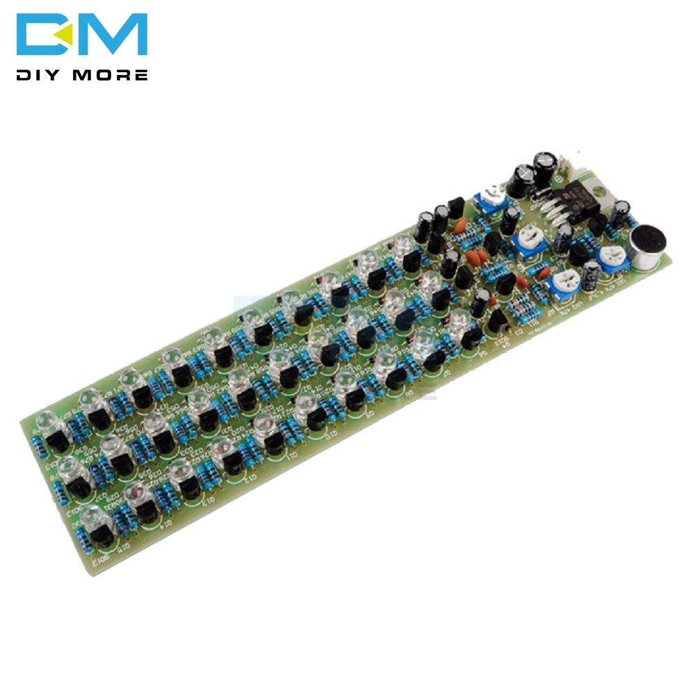
Red Blue Green RGB Voice Control Indicator Level 3 Sections Module Electronic Production DIY Kit Electronic PCB Board


Red Blue Green RGB Voice Control Indicator Level 3 Sections Module Electronic Production DIY Kit Electronic PCB Board
brand: DIYTECH SKU:DT2523-03
Regular price
$13.39
Sale price
$12.27
![]()
- guaranteeQuality checked
- Special gift cardsSpecial gift cards
- Free return Within 60 days
- Consultancyservice@diytech.cc
1. Features
Power Voltage: 9V--15V;
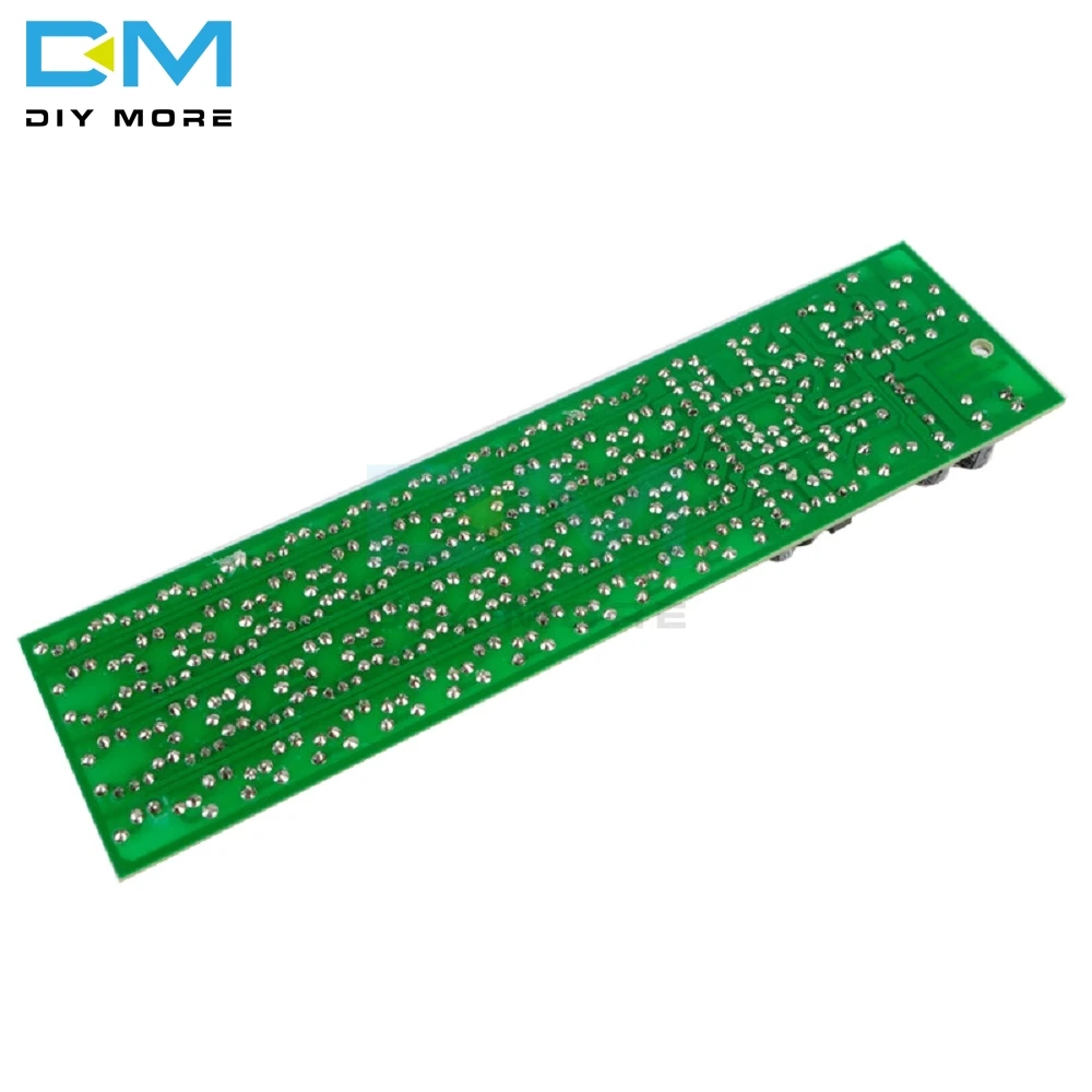
PCB Dimensions: 160mm*42mm.
2. Circuits Principle
The circuit is mainly composed by Power Circuit, Audio Amplifier Circuit, Frequency Dividing Circuit and LED Driver Circuit.
1) Power Circuit: The power output voltage is 9V--15V. D1 can avoid the demage of three terminal regulator when the power polarity is connected in a wrong way. After the C4's filtering , L7806 three terminal regulator will provide the whole circuit with a stable voltage of 6V.
2 ) Audio Amplifier Circuit: Electret microphone MK1 transfers the obtained sound to electric signal which will be amplifed twice by Q1 and Q2. At this time, UR1 can adjust the size of Q2 signal in order to adjust the sensitivity of the whole circuit.
3 ) Frequency Dividing Circuit: Three frequency dividing circuits is added to indicate the electrical level on the different frequency, as it's featured with three sections of LED indicator in a seperate way. VR2, VR3 and VR4 are used for adjusting the sensitivity of LED indicator on the different frequency. The sound signal from three different frequency can be distinguished according to the different capability of C6, C10 and C11. Q4, Q5 and Q18 collectors can obtain three different frequency and the voltages after dividing and amplifying by diode and transistor. The level of voltage depends on the size of the sound from outside.
4 ) LED Driver Circuit: There are 9 pieces of 1N4148 diode in each frequency. If the sound is louder, the higher voltage will be obtained by Q4,Q5 and Q18 connector and more 1N4148 start work. Then more LEDs can light.
3. Components List

4. Circuit Diagram


?
?
?
?
?
?
?
Other Customers also buy:
-

 Translation missing: en.products.product.regular_price
$5.99 On Sale{"id":4521854402647,"title":"Red Blue Green RGB Voice Control Indicator Level 3 Sections Module Electronic Production DIY Kit Electronic PCB Board","handle":"red-blue-green-rgb-voice-control-indicator-level-3-sections-module-electronic-production-diy-kit-electronic-pcb-board","description":"\u003cp\u003e \u003c\/p\u003e\n\u003cdiv\u003e\u003cspan\u003e\u003cstrong\u003e1. Features\u003c\/strong\u003e\u003c\/span\u003e\u003c\/div\u003e\n\u003cdiv\u003e\u003cspan\u003ePower Voltage: 9V--15V;\u003c\/span\u003e\u003c\/div\u003e\n\u003cdiv\u003e\u003cspan\u003ePCB Dimensions: 160mm*42mm.\u003c\/span\u003e\u003c\/div\u003e\n\u003cdiv\u003e\u003cspan\u003e \u003c\/span\u003e\u003c\/div\u003e\n\u003cdiv\u003e\u003cspan\u003e\u003cstrong\u003e2. Circuits Principle\u003c\/strong\u003e\u003c\/span\u003e\u003c\/div\u003e\n\u003cdiv\u003e\u003cspan\u003eThe circuit is mainly composed by Power Circuit, Audio Amplifier Circuit, Frequency Dividing Circuit and LED Driver Circuit.\u003c\/span\u003e\u003c\/div\u003e\n\u003cdiv\u003e\u003cspan\u003e1) Power Circuit: The power output voltage is 9V--15V. D1 can avoid the demage of three terminal regulator when the power polarity is connected in a wrong way. After the C4's filtering , L7806 three terminal regulator will provide the whole circuit with a stable voltage of 6V.\u003c\/span\u003e\u003c\/div\u003e\n\u003cdiv\u003e\n\u003cspan\u003e2\u003c\/span\u003e\u003cspan\u003e \u003c\/span\u003e\u003cspan\u003e) \u003c\/span\u003e\u003cspan\u003eAudio Amplifier Circuit: Electret microphone MK1 transfers the obtained sound to electric signal which will be amplifed twice by Q1 and Q2. At this time, UR1 can adjust the size of Q2 signal in order to adjust the sensitivity of the whole circuit.\u003c\/span\u003e\n\u003c\/div\u003e\n\u003cdiv\u003e\n\u003cspan\u003e3\u003c\/span\u003e\u003cspan\u003e \u003c\/span\u003e\u003cspan\u003e) \u003c\/span\u003e\u003cspan\u003eFrequency Dividing Circuit: Three frequency dividing circuits is added to indicate the electrical level on the different frequency, as it's featured with three sections of LED indicator in a seperate way. VR2, VR3 and VR4 are used for adjusting the sensitivity of LED indicator on the different frequency. The sound signal from three different frequency can be distinguished according to the different capability of C6, C10 and C11. Q4, Q5 and Q18 collectors can obtain three different frequency and the voltages after dividing and amplifying by diode and transistor. The level of voltage depends on the size of the sound from outside.\u003c\/span\u003e\n\u003c\/div\u003e\n\u003cdiv\u003e\n\u003cspan\u003e4\u003c\/span\u003e\u003cspan\u003e \u003c\/span\u003e\u003cspan\u003e) \u003c\/span\u003e\u003cspan\u003eLED Driver Circuit: There are 9 pieces of 1N4148 diode in each frequency. If the sound is louder, the higher voltage will be obtained by Q4,Q5 and Q18 connector and more 1N4148 start work. Then more LEDs can light.\u003c\/span\u003e\n\u003c\/div\u003e\n\u003cdiv\u003e\u003cspan\u003e \u003c\/span\u003e\u003c\/div\u003e\n\u003cdiv\u003e\u003cspan\u003e \u003c\/span\u003e\u003c\/div\u003e\n\u003cdiv\u003e\u003cstrong\u003e\u003cspan\u003e3. Components List\u003c\/span\u003e\u003c\/strong\u003e\u003c\/div\u003e\n\u003cdiv\u003e\u003cspan\u003e\u003cimg alt=\"1748-m-1\" src=\"https:\/\/ae01.alicdn.com\/kf\/HTB1fZFhibuWBuNjSszgq6z8jVXaE.jpg\" width=\"586\" height=\"462\"\u003e\u003c\/span\u003e\u003c\/div\u003e\n\u003cdiv\u003e\u003cspan\u003e \u003c\/span\u003e\u003c\/div\u003e\n\u003cdiv\u003e\u003cstrong\u003e\u003cspan\u003e4. Circuit Diagram\u003c\/span\u003e\u003c\/strong\u003e\u003c\/div\u003e\n\u003cdiv\u003e\u003cspan\u003e\u003cimg alt=\"1748-m-2\" src=\"https:\/\/ae01.alicdn.com\/kf\/HTB1uZ0LieySBuNjy1zdq6xPxFXaa.jpg\"\u003e\u003c\/span\u003e\u003c\/div\u003e\n\u003cdiv\u003e\n\u003cp\u003e\u003cimg src=\"http:\/\/ae01.alicdn.com\/kf\/HTB1MQtSatjvK1RjSspiq6AEqXXaZ.jpg\" width=\"1000\"\u003e\u003c\/p\u003e\n\u003cp\u003e\u003cimg src=\"http:\/\/ae01.alicdn.com\/kf\/HTB1EspMaE_rK1Rjy0Fcq6zEvVXaY.jpg\" width=\"1000\"\u003e\u003c\/p\u003e\n\u003cp\u003e\u003cimg src=\"http:\/\/ae01.alicdn.com\/kf\/HTB14OpOavfsK1RjSszbq6AqBXXai.jpg\" width=\"1000\"\u003e\u003c\/p\u003e\n\u003c\/div\u003e\n\u003cdiv\u003e?\u003c\/div\u003e\n\u003cdiv\u003e?\u003c\/div\u003e\n\u003cdiv\u003e?\u003c\/div\u003e\n\u003cdiv\u003e?\u003c\/div\u003e\n\u003cdiv\u003e?\u003c\/div\u003e\n\u003cdiv\u003e?\u003c\/div\u003e\n\u003cdiv\u003e?\u003c\/div\u003e\n\u003cdiv\u003e\n\u003cp\u003e\u003cbr\u003e\u003c\/p\u003e\n\u003cp\u003e\u003cbr\u003e\u003c\/p\u003e\n\u003c\/div\u003e","published_at":"2020-05-22T21:30:02+08:00","created_at":"2020-05-22T21:30:03+08:00","vendor":"DIYTECH","type":"Circuit board","tags":["Amplifier","Kits"],"price":1227,"price_min":1227,"price_max":3763,"available":true,"price_varies":true,"compare_at_price":1339,"compare_at_price_min":1339,"compare_at_price_max":1339,"compare_at_price_varies":false,"variants":[{"id":32208963928151,"title":"3pcs","option1":"3pcs","option2":null,"option3":null,"sku":"DT2523-03","requires_shipping":true,"taxable":false,"featured_image":null,"available":true,"name":"Red Blue Green RGB Voice Control Indicator Level 3 Sections Module Electronic Production DIY Kit Electronic PCB Board - 3pcs","public_title":"3pcs","options":["3pcs"],"price":1227,"weight":159,"compare_at_price":1339,"inventory_management":null,"barcode":"","requires_selling_plan":false,"selling_plan_allocations":[]},{"id":32208963960919,"title":"10pcs","option1":"10pcs","option2":null,"option3":null,"sku":"DT2523-10","requires_shipping":true,"taxable":false,"featured_image":null,"available":true,"name":"Red Blue Green RGB Voice Control Indicator Level 3 Sections Module Electronic Production DIY Kit Electronic PCB Board - 10pcs","public_title":"10pcs","options":["10pcs"],"price":3763,"weight":530,"compare_at_price":null,"inventory_management":null,"barcode":"","requires_selling_plan":false,"selling_plan_allocations":[]}],"images":["\/\/diytech.cc\/cdn\/shop\/products\/HTB1MQtSatjvK1RjSspiq6AEqXXaZ.jpg?v=1590592329","\/\/diytech.cc\/cdn\/shop\/products\/HTB1EspMaE_rK1Rjy0Fcq6zEvVXaY.jpg?v=1590592341"],"featured_image":"\/\/diytech.cc\/cdn\/shop\/products\/HTB1MQtSatjvK1RjSspiq6AEqXXaZ.jpg?v=1590592329","options":["Batch"],"media":[{"alt":null,"id":6312219312215,"position":1,"preview_image":{"aspect_ratio":1.0,"height":1000,"width":1000,"src":"\/\/diytech.cc\/cdn\/shop\/products\/HTB1MQtSatjvK1RjSspiq6AEqXXaZ.jpg?v=1590592329"},"aspect_ratio":1.0,"height":1000,"media_type":"image","src":"\/\/diytech.cc\/cdn\/shop\/products\/HTB1MQtSatjvK1RjSspiq6AEqXXaZ.jpg?v=1590592329","width":1000},{"alt":null,"id":6312220590167,"position":2,"preview_image":{"aspect_ratio":1.0,"height":1000,"width":1000,"src":"\/\/diytech.cc\/cdn\/shop\/products\/HTB1EspMaE_rK1Rjy0Fcq6zEvVXaY.jpg?v=1590592341"},"aspect_ratio":1.0,"height":1000,"media_type":"image","src":"\/\/diytech.cc\/cdn\/shop\/products\/HTB1EspMaE_rK1Rjy0Fcq6zEvVXaY.jpg?v=1590592341","width":1000}],"requires_selling_plan":false,"selling_plan_groups":[],"content":"\u003cp\u003e \u003c\/p\u003e\n\u003cdiv\u003e\u003cspan\u003e\u003cstrong\u003e1. Features\u003c\/strong\u003e\u003c\/span\u003e\u003c\/div\u003e\n\u003cdiv\u003e\u003cspan\u003ePower Voltage: 9V--15V;\u003c\/span\u003e\u003c\/div\u003e\n\u003cdiv\u003e\u003cspan\u003ePCB Dimensions: 160mm*42mm.\u003c\/span\u003e\u003c\/div\u003e\n\u003cdiv\u003e\u003cspan\u003e \u003c\/span\u003e\u003c\/div\u003e\n\u003cdiv\u003e\u003cspan\u003e\u003cstrong\u003e2. Circuits Principle\u003c\/strong\u003e\u003c\/span\u003e\u003c\/div\u003e\n\u003cdiv\u003e\u003cspan\u003eThe circuit is mainly composed by Power Circuit, Audio Amplifier Circuit, Frequency Dividing Circuit and LED Driver Circuit.\u003c\/span\u003e\u003c\/div\u003e\n\u003cdiv\u003e\u003cspan\u003e1) Power Circuit: The power output voltage is 9V--15V. D1 can avoid the demage of three terminal regulator when the power polarity is connected in a wrong way. After the C4's filtering , L7806 three terminal regulator will provide the whole circuit with a stable voltage of 6V.\u003c\/span\u003e\u003c\/div\u003e\n\u003cdiv\u003e\n\u003cspan\u003e2\u003c\/span\u003e\u003cspan\u003e \u003c\/span\u003e\u003cspan\u003e) \u003c\/span\u003e\u003cspan\u003eAudio Amplifier Circuit: Electret microphone MK1 transfers the obtained sound to electric signal which will be amplifed twice by Q1 and Q2. At this time, UR1 can adjust the size of Q2 signal in order to adjust the sensitivity of the whole circuit.\u003c\/span\u003e\n\u003c\/div\u003e\n\u003cdiv\u003e\n\u003cspan\u003e3\u003c\/span\u003e\u003cspan\u003e \u003c\/span\u003e\u003cspan\u003e) \u003c\/span\u003e\u003cspan\u003eFrequency Dividing Circuit: Three frequency dividing circuits is added to indicate the electrical level on the different frequency, as it's featured with three sections of LED indicator in a seperate way. VR2, VR3 and VR4 are used for adjusting the sensitivity of LED indicator on the different frequency. The sound signal from three different frequency can be distinguished according to the different capability of C6, C10 and C11. Q4, Q5 and Q18 collectors can obtain three different frequency and the voltages after dividing and amplifying by diode and transistor. The level of voltage depends on the size of the sound from outside.\u003c\/span\u003e\n\u003c\/div\u003e\n\u003cdiv\u003e\n\u003cspan\u003e4\u003c\/span\u003e\u003cspan\u003e \u003c\/span\u003e\u003cspan\u003e) \u003c\/span\u003e\u003cspan\u003eLED Driver Circuit: There are 9 pieces of 1N4148 diode in each frequency. If the sound is louder, the higher voltage will be obtained by Q4,Q5 and Q18 connector and more 1N4148 start work. Then more LEDs can light.\u003c\/span\u003e\n\u003c\/div\u003e\n\u003cdiv\u003e\u003cspan\u003e \u003c\/span\u003e\u003c\/div\u003e\n\u003cdiv\u003e\u003cspan\u003e \u003c\/span\u003e\u003c\/div\u003e\n\u003cdiv\u003e\u003cstrong\u003e\u003cspan\u003e3. Components List\u003c\/span\u003e\u003c\/strong\u003e\u003c\/div\u003e\n\u003cdiv\u003e\u003cspan\u003e\u003cimg alt=\"1748-m-1\" src=\"https:\/\/ae01.alicdn.com\/kf\/HTB1fZFhibuWBuNjSszgq6z8jVXaE.jpg\" width=\"586\" height=\"462\"\u003e\u003c\/span\u003e\u003c\/div\u003e\n\u003cdiv\u003e\u003cspan\u003e \u003c\/span\u003e\u003c\/div\u003e\n\u003cdiv\u003e\u003cstrong\u003e\u003cspan\u003e4. Circuit Diagram\u003c\/span\u003e\u003c\/strong\u003e\u003c\/div\u003e\n\u003cdiv\u003e\u003cspan\u003e\u003cimg alt=\"1748-m-2\" src=\"https:\/\/ae01.alicdn.com\/kf\/HTB1uZ0LieySBuNjy1zdq6xPxFXaa.jpg\"\u003e\u003c\/span\u003e\u003c\/div\u003e\n\u003cdiv\u003e\n\u003cp\u003e\u003cimg src=\"http:\/\/ae01.alicdn.com\/kf\/HTB1MQtSatjvK1RjSspiq6AEqXXaZ.jpg\" width=\"1000\"\u003e\u003c\/p\u003e\n\u003cp\u003e\u003cimg src=\"http:\/\/ae01.alicdn.com\/kf\/HTB1EspMaE_rK1Rjy0Fcq6zEvVXaY.jpg\" width=\"1000\"\u003e\u003c\/p\u003e\n\u003cp\u003e\u003cimg src=\"http:\/\/ae01.alicdn.com\/kf\/HTB14OpOavfsK1RjSszbq6AqBXXai.jpg\" width=\"1000\"\u003e\u003c\/p\u003e\n\u003c\/div\u003e\n\u003cdiv\u003e?\u003c\/div\u003e\n\u003cdiv\u003e?\u003c\/div\u003e\n\u003cdiv\u003e?\u003c\/div\u003e\n\u003cdiv\u003e?\u003c\/div\u003e\n\u003cdiv\u003e?\u003c\/div\u003e\n\u003cdiv\u003e?\u003c\/div\u003e\n\u003cdiv\u003e?\u003c\/div\u003e\n\u003cdiv\u003e\n\u003cp\u003e\u003cbr\u003e\u003c\/p\u003e\n\u003cp\u003e\u003cbr\u003e\u003c\/p\u003e\n\u003c\/div\u003e"} -

 Translation missing: en.products.product.regular_price
$2.99$1.99 On Sale{"id":4521854402647,"title":"Red Blue Green RGB Voice Control Indicator Level 3 Sections Module Electronic Production DIY Kit Electronic PCB Board","handle":"red-blue-green-rgb-voice-control-indicator-level-3-sections-module-electronic-production-diy-kit-electronic-pcb-board","description":"\u003cp\u003e \u003c\/p\u003e\n\u003cdiv\u003e\u003cspan\u003e\u003cstrong\u003e1. Features\u003c\/strong\u003e\u003c\/span\u003e\u003c\/div\u003e\n\u003cdiv\u003e\u003cspan\u003ePower Voltage: 9V--15V;\u003c\/span\u003e\u003c\/div\u003e\n\u003cdiv\u003e\u003cspan\u003ePCB Dimensions: 160mm*42mm.\u003c\/span\u003e\u003c\/div\u003e\n\u003cdiv\u003e\u003cspan\u003e \u003c\/span\u003e\u003c\/div\u003e\n\u003cdiv\u003e\u003cspan\u003e\u003cstrong\u003e2. Circuits Principle\u003c\/strong\u003e\u003c\/span\u003e\u003c\/div\u003e\n\u003cdiv\u003e\u003cspan\u003eThe circuit is mainly composed by Power Circuit, Audio Amplifier Circuit, Frequency Dividing Circuit and LED Driver Circuit.\u003c\/span\u003e\u003c\/div\u003e\n\u003cdiv\u003e\u003cspan\u003e1) Power Circuit: The power output voltage is 9V--15V. D1 can avoid the demage of three terminal regulator when the power polarity is connected in a wrong way. After the C4's filtering , L7806 three terminal regulator will provide the whole circuit with a stable voltage of 6V.\u003c\/span\u003e\u003c\/div\u003e\n\u003cdiv\u003e\n\u003cspan\u003e2\u003c\/span\u003e\u003cspan\u003e \u003c\/span\u003e\u003cspan\u003e) \u003c\/span\u003e\u003cspan\u003eAudio Amplifier Circuit: Electret microphone MK1 transfers the obtained sound to electric signal which will be amplifed twice by Q1 and Q2. At this time, UR1 can adjust the size of Q2 signal in order to adjust the sensitivity of the whole circuit.\u003c\/span\u003e\n\u003c\/div\u003e\n\u003cdiv\u003e\n\u003cspan\u003e3\u003c\/span\u003e\u003cspan\u003e \u003c\/span\u003e\u003cspan\u003e) \u003c\/span\u003e\u003cspan\u003eFrequency Dividing Circuit: Three frequency dividing circuits is added to indicate the electrical level on the different frequency, as it's featured with three sections of LED indicator in a seperate way. VR2, VR3 and VR4 are used for adjusting the sensitivity of LED indicator on the different frequency. The sound signal from three different frequency can be distinguished according to the different capability of C6, C10 and C11. Q4, Q5 and Q18 collectors can obtain three different frequency and the voltages after dividing and amplifying by diode and transistor. The level of voltage depends on the size of the sound from outside.\u003c\/span\u003e\n\u003c\/div\u003e\n\u003cdiv\u003e\n\u003cspan\u003e4\u003c\/span\u003e\u003cspan\u003e \u003c\/span\u003e\u003cspan\u003e) \u003c\/span\u003e\u003cspan\u003eLED Driver Circuit: There are 9 pieces of 1N4148 diode in each frequency. If the sound is louder, the higher voltage will be obtained by Q4,Q5 and Q18 connector and more 1N4148 start work. Then more LEDs can light.\u003c\/span\u003e\n\u003c\/div\u003e\n\u003cdiv\u003e\u003cspan\u003e \u003c\/span\u003e\u003c\/div\u003e\n\u003cdiv\u003e\u003cspan\u003e \u003c\/span\u003e\u003c\/div\u003e\n\u003cdiv\u003e\u003cstrong\u003e\u003cspan\u003e3. Components List\u003c\/span\u003e\u003c\/strong\u003e\u003c\/div\u003e\n\u003cdiv\u003e\u003cspan\u003e\u003cimg alt=\"1748-m-1\" src=\"https:\/\/ae01.alicdn.com\/kf\/HTB1fZFhibuWBuNjSszgq6z8jVXaE.jpg\" width=\"586\" height=\"462\"\u003e\u003c\/span\u003e\u003c\/div\u003e\n\u003cdiv\u003e\u003cspan\u003e \u003c\/span\u003e\u003c\/div\u003e\n\u003cdiv\u003e\u003cstrong\u003e\u003cspan\u003e4. Circuit Diagram\u003c\/span\u003e\u003c\/strong\u003e\u003c\/div\u003e\n\u003cdiv\u003e\u003cspan\u003e\u003cimg alt=\"1748-m-2\" src=\"https:\/\/ae01.alicdn.com\/kf\/HTB1uZ0LieySBuNjy1zdq6xPxFXaa.jpg\"\u003e\u003c\/span\u003e\u003c\/div\u003e\n\u003cdiv\u003e\n\u003cp\u003e\u003cimg src=\"http:\/\/ae01.alicdn.com\/kf\/HTB1MQtSatjvK1RjSspiq6AEqXXaZ.jpg\" width=\"1000\"\u003e\u003c\/p\u003e\n\u003cp\u003e\u003cimg src=\"http:\/\/ae01.alicdn.com\/kf\/HTB1EspMaE_rK1Rjy0Fcq6zEvVXaY.jpg\" width=\"1000\"\u003e\u003c\/p\u003e\n\u003cp\u003e\u003cimg src=\"http:\/\/ae01.alicdn.com\/kf\/HTB14OpOavfsK1RjSszbq6AqBXXai.jpg\" width=\"1000\"\u003e\u003c\/p\u003e\n\u003c\/div\u003e\n\u003cdiv\u003e?\u003c\/div\u003e\n\u003cdiv\u003e?\u003c\/div\u003e\n\u003cdiv\u003e?\u003c\/div\u003e\n\u003cdiv\u003e?\u003c\/div\u003e\n\u003cdiv\u003e?\u003c\/div\u003e\n\u003cdiv\u003e?\u003c\/div\u003e\n\u003cdiv\u003e?\u003c\/div\u003e\n\u003cdiv\u003e\n\u003cp\u003e\u003cbr\u003e\u003c\/p\u003e\n\u003cp\u003e\u003cbr\u003e\u003c\/p\u003e\n\u003c\/div\u003e","published_at":"2020-05-22T21:30:02+08:00","created_at":"2020-05-22T21:30:03+08:00","vendor":"DIYTECH","type":"Circuit board","tags":["Amplifier","Kits"],"price":1227,"price_min":1227,"price_max":3763,"available":true,"price_varies":true,"compare_at_price":1339,"compare_at_price_min":1339,"compare_at_price_max":1339,"compare_at_price_varies":false,"variants":[{"id":32208963928151,"title":"3pcs","option1":"3pcs","option2":null,"option3":null,"sku":"DT2523-03","requires_shipping":true,"taxable":false,"featured_image":null,"available":true,"name":"Red Blue Green RGB Voice Control Indicator Level 3 Sections Module Electronic Production DIY Kit Electronic PCB Board - 3pcs","public_title":"3pcs","options":["3pcs"],"price":1227,"weight":159,"compare_at_price":1339,"inventory_management":null,"barcode":"","requires_selling_plan":false,"selling_plan_allocations":[]},{"id":32208963960919,"title":"10pcs","option1":"10pcs","option2":null,"option3":null,"sku":"DT2523-10","requires_shipping":true,"taxable":false,"featured_image":null,"available":true,"name":"Red Blue Green RGB Voice Control Indicator Level 3 Sections Module Electronic Production DIY Kit Electronic PCB Board - 10pcs","public_title":"10pcs","options":["10pcs"],"price":3763,"weight":530,"compare_at_price":null,"inventory_management":null,"barcode":"","requires_selling_plan":false,"selling_plan_allocations":[]}],"images":["\/\/diytech.cc\/cdn\/shop\/products\/HTB1MQtSatjvK1RjSspiq6AEqXXaZ.jpg?v=1590592329","\/\/diytech.cc\/cdn\/shop\/products\/HTB1EspMaE_rK1Rjy0Fcq6zEvVXaY.jpg?v=1590592341"],"featured_image":"\/\/diytech.cc\/cdn\/shop\/products\/HTB1MQtSatjvK1RjSspiq6AEqXXaZ.jpg?v=1590592329","options":["Batch"],"media":[{"alt":null,"id":6312219312215,"position":1,"preview_image":{"aspect_ratio":1.0,"height":1000,"width":1000,"src":"\/\/diytech.cc\/cdn\/shop\/products\/HTB1MQtSatjvK1RjSspiq6AEqXXaZ.jpg?v=1590592329"},"aspect_ratio":1.0,"height":1000,"media_type":"image","src":"\/\/diytech.cc\/cdn\/shop\/products\/HTB1MQtSatjvK1RjSspiq6AEqXXaZ.jpg?v=1590592329","width":1000},{"alt":null,"id":6312220590167,"position":2,"preview_image":{"aspect_ratio":1.0,"height":1000,"width":1000,"src":"\/\/diytech.cc\/cdn\/shop\/products\/HTB1EspMaE_rK1Rjy0Fcq6zEvVXaY.jpg?v=1590592341"},"aspect_ratio":1.0,"height":1000,"media_type":"image","src":"\/\/diytech.cc\/cdn\/shop\/products\/HTB1EspMaE_rK1Rjy0Fcq6zEvVXaY.jpg?v=1590592341","width":1000}],"requires_selling_plan":false,"selling_plan_groups":[],"content":"\u003cp\u003e \u003c\/p\u003e\n\u003cdiv\u003e\u003cspan\u003e\u003cstrong\u003e1. Features\u003c\/strong\u003e\u003c\/span\u003e\u003c\/div\u003e\n\u003cdiv\u003e\u003cspan\u003ePower Voltage: 9V--15V;\u003c\/span\u003e\u003c\/div\u003e\n\u003cdiv\u003e\u003cspan\u003ePCB Dimensions: 160mm*42mm.\u003c\/span\u003e\u003c\/div\u003e\n\u003cdiv\u003e\u003cspan\u003e \u003c\/span\u003e\u003c\/div\u003e\n\u003cdiv\u003e\u003cspan\u003e\u003cstrong\u003e2. Circuits Principle\u003c\/strong\u003e\u003c\/span\u003e\u003c\/div\u003e\n\u003cdiv\u003e\u003cspan\u003eThe circuit is mainly composed by Power Circuit, Audio Amplifier Circuit, Frequency Dividing Circuit and LED Driver Circuit.\u003c\/span\u003e\u003c\/div\u003e\n\u003cdiv\u003e\u003cspan\u003e1) Power Circuit: The power output voltage is 9V--15V. D1 can avoid the demage of three terminal regulator when the power polarity is connected in a wrong way. After the C4's filtering , L7806 three terminal regulator will provide the whole circuit with a stable voltage of 6V.\u003c\/span\u003e\u003c\/div\u003e\n\u003cdiv\u003e\n\u003cspan\u003e2\u003c\/span\u003e\u003cspan\u003e \u003c\/span\u003e\u003cspan\u003e) \u003c\/span\u003e\u003cspan\u003eAudio Amplifier Circuit: Electret microphone MK1 transfers the obtained sound to electric signal which will be amplifed twice by Q1 and Q2. At this time, UR1 can adjust the size of Q2 signal in order to adjust the sensitivity of the whole circuit.\u003c\/span\u003e\n\u003c\/div\u003e\n\u003cdiv\u003e\n\u003cspan\u003e3\u003c\/span\u003e\u003cspan\u003e \u003c\/span\u003e\u003cspan\u003e) \u003c\/span\u003e\u003cspan\u003eFrequency Dividing Circuit: Three frequency dividing circuits is added to indicate the electrical level on the different frequency, as it's featured with three sections of LED indicator in a seperate way. VR2, VR3 and VR4 are used for adjusting the sensitivity of LED indicator on the different frequency. The sound signal from three different frequency can be distinguished according to the different capability of C6, C10 and C11. Q4, Q5 and Q18 collectors can obtain three different frequency and the voltages after dividing and amplifying by diode and transistor. The level of voltage depends on the size of the sound from outside.\u003c\/span\u003e\n\u003c\/div\u003e\n\u003cdiv\u003e\n\u003cspan\u003e4\u003c\/span\u003e\u003cspan\u003e \u003c\/span\u003e\u003cspan\u003e) \u003c\/span\u003e\u003cspan\u003eLED Driver Circuit: There are 9 pieces of 1N4148 diode in each frequency. If the sound is louder, the higher voltage will be obtained by Q4,Q5 and Q18 connector and more 1N4148 start work. Then more LEDs can light.\u003c\/span\u003e\n\u003c\/div\u003e\n\u003cdiv\u003e\u003cspan\u003e \u003c\/span\u003e\u003c\/div\u003e\n\u003cdiv\u003e\u003cspan\u003e \u003c\/span\u003e\u003c\/div\u003e\n\u003cdiv\u003e\u003cstrong\u003e\u003cspan\u003e3. Components List\u003c\/span\u003e\u003c\/strong\u003e\u003c\/div\u003e\n\u003cdiv\u003e\u003cspan\u003e\u003cimg alt=\"1748-m-1\" src=\"https:\/\/ae01.alicdn.com\/kf\/HTB1fZFhibuWBuNjSszgq6z8jVXaE.jpg\" width=\"586\" height=\"462\"\u003e\u003c\/span\u003e\u003c\/div\u003e\n\u003cdiv\u003e\u003cspan\u003e \u003c\/span\u003e\u003c\/div\u003e\n\u003cdiv\u003e\u003cstrong\u003e\u003cspan\u003e4. Circuit Diagram\u003c\/span\u003e\u003c\/strong\u003e\u003c\/div\u003e\n\u003cdiv\u003e\u003cspan\u003e\u003cimg alt=\"1748-m-2\" src=\"https:\/\/ae01.alicdn.com\/kf\/HTB1uZ0LieySBuNjy1zdq6xPxFXaa.jpg\"\u003e\u003c\/span\u003e\u003c\/div\u003e\n\u003cdiv\u003e\n\u003cp\u003e\u003cimg src=\"http:\/\/ae01.alicdn.com\/kf\/HTB1MQtSatjvK1RjSspiq6AEqXXaZ.jpg\" width=\"1000\"\u003e\u003c\/p\u003e\n\u003cp\u003e\u003cimg src=\"http:\/\/ae01.alicdn.com\/kf\/HTB1EspMaE_rK1Rjy0Fcq6zEvVXaY.jpg\" width=\"1000\"\u003e\u003c\/p\u003e\n\u003cp\u003e\u003cimg src=\"http:\/\/ae01.alicdn.com\/kf\/HTB14OpOavfsK1RjSszbq6AqBXXai.jpg\" width=\"1000\"\u003e\u003c\/p\u003e\n\u003c\/div\u003e\n\u003cdiv\u003e?\u003c\/div\u003e\n\u003cdiv\u003e?\u003c\/div\u003e\n\u003cdiv\u003e?\u003c\/div\u003e\n\u003cdiv\u003e?\u003c\/div\u003e\n\u003cdiv\u003e?\u003c\/div\u003e\n\u003cdiv\u003e?\u003c\/div\u003e\n\u003cdiv\u003e?\u003c\/div\u003e\n\u003cdiv\u003e\n\u003cp\u003e\u003cbr\u003e\u003c\/p\u003e\n\u003cp\u003e\u003cbr\u003e\u003c\/p\u003e\n\u003c\/div\u003e"} -

 Translation missing: en.products.product.regular_price
$1.19 On Sale{"id":4521854402647,"title":"Red Blue Green RGB Voice Control Indicator Level 3 Sections Module Electronic Production DIY Kit Electronic PCB Board","handle":"red-blue-green-rgb-voice-control-indicator-level-3-sections-module-electronic-production-diy-kit-electronic-pcb-board","description":"\u003cp\u003e \u003c\/p\u003e\n\u003cdiv\u003e\u003cspan\u003e\u003cstrong\u003e1. Features\u003c\/strong\u003e\u003c\/span\u003e\u003c\/div\u003e\n\u003cdiv\u003e\u003cspan\u003ePower Voltage: 9V--15V;\u003c\/span\u003e\u003c\/div\u003e\n\u003cdiv\u003e\u003cspan\u003ePCB Dimensions: 160mm*42mm.\u003c\/span\u003e\u003c\/div\u003e\n\u003cdiv\u003e\u003cspan\u003e \u003c\/span\u003e\u003c\/div\u003e\n\u003cdiv\u003e\u003cspan\u003e\u003cstrong\u003e2. Circuits Principle\u003c\/strong\u003e\u003c\/span\u003e\u003c\/div\u003e\n\u003cdiv\u003e\u003cspan\u003eThe circuit is mainly composed by Power Circuit, Audio Amplifier Circuit, Frequency Dividing Circuit and LED Driver Circuit.\u003c\/span\u003e\u003c\/div\u003e\n\u003cdiv\u003e\u003cspan\u003e1) Power Circuit: The power output voltage is 9V--15V. D1 can avoid the demage of three terminal regulator when the power polarity is connected in a wrong way. After the C4's filtering , L7806 three terminal regulator will provide the whole circuit with a stable voltage of 6V.\u003c\/span\u003e\u003c\/div\u003e\n\u003cdiv\u003e\n\u003cspan\u003e2\u003c\/span\u003e\u003cspan\u003e \u003c\/span\u003e\u003cspan\u003e) \u003c\/span\u003e\u003cspan\u003eAudio Amplifier Circuit: Electret microphone MK1 transfers the obtained sound to electric signal which will be amplifed twice by Q1 and Q2. At this time, UR1 can adjust the size of Q2 signal in order to adjust the sensitivity of the whole circuit.\u003c\/span\u003e\n\u003c\/div\u003e\n\u003cdiv\u003e\n\u003cspan\u003e3\u003c\/span\u003e\u003cspan\u003e \u003c\/span\u003e\u003cspan\u003e) \u003c\/span\u003e\u003cspan\u003eFrequency Dividing Circuit: Three frequency dividing circuits is added to indicate the electrical level on the different frequency, as it's featured with three sections of LED indicator in a seperate way. VR2, VR3 and VR4 are used for adjusting the sensitivity of LED indicator on the different frequency. The sound signal from three different frequency can be distinguished according to the different capability of C6, C10 and C11. Q4, Q5 and Q18 collectors can obtain three different frequency and the voltages after dividing and amplifying by diode and transistor. The level of voltage depends on the size of the sound from outside.\u003c\/span\u003e\n\u003c\/div\u003e\n\u003cdiv\u003e\n\u003cspan\u003e4\u003c\/span\u003e\u003cspan\u003e \u003c\/span\u003e\u003cspan\u003e) \u003c\/span\u003e\u003cspan\u003eLED Driver Circuit: There are 9 pieces of 1N4148 diode in each frequency. If the sound is louder, the higher voltage will be obtained by Q4,Q5 and Q18 connector and more 1N4148 start work. Then more LEDs can light.\u003c\/span\u003e\n\u003c\/div\u003e\n\u003cdiv\u003e\u003cspan\u003e \u003c\/span\u003e\u003c\/div\u003e\n\u003cdiv\u003e\u003cspan\u003e \u003c\/span\u003e\u003c\/div\u003e\n\u003cdiv\u003e\u003cstrong\u003e\u003cspan\u003e3. Components List\u003c\/span\u003e\u003c\/strong\u003e\u003c\/div\u003e\n\u003cdiv\u003e\u003cspan\u003e\u003cimg alt=\"1748-m-1\" src=\"https:\/\/ae01.alicdn.com\/kf\/HTB1fZFhibuWBuNjSszgq6z8jVXaE.jpg\" width=\"586\" height=\"462\"\u003e\u003c\/span\u003e\u003c\/div\u003e\n\u003cdiv\u003e\u003cspan\u003e \u003c\/span\u003e\u003c\/div\u003e\n\u003cdiv\u003e\u003cstrong\u003e\u003cspan\u003e4. Circuit Diagram\u003c\/span\u003e\u003c\/strong\u003e\u003c\/div\u003e\n\u003cdiv\u003e\u003cspan\u003e\u003cimg alt=\"1748-m-2\" src=\"https:\/\/ae01.alicdn.com\/kf\/HTB1uZ0LieySBuNjy1zdq6xPxFXaa.jpg\"\u003e\u003c\/span\u003e\u003c\/div\u003e\n\u003cdiv\u003e\n\u003cp\u003e\u003cimg src=\"http:\/\/ae01.alicdn.com\/kf\/HTB1MQtSatjvK1RjSspiq6AEqXXaZ.jpg\" width=\"1000\"\u003e\u003c\/p\u003e\n\u003cp\u003e\u003cimg src=\"http:\/\/ae01.alicdn.com\/kf\/HTB1EspMaE_rK1Rjy0Fcq6zEvVXaY.jpg\" width=\"1000\"\u003e\u003c\/p\u003e\n\u003cp\u003e\u003cimg src=\"http:\/\/ae01.alicdn.com\/kf\/HTB14OpOavfsK1RjSszbq6AqBXXai.jpg\" width=\"1000\"\u003e\u003c\/p\u003e\n\u003c\/div\u003e\n\u003cdiv\u003e?\u003c\/div\u003e\n\u003cdiv\u003e?\u003c\/div\u003e\n\u003cdiv\u003e?\u003c\/div\u003e\n\u003cdiv\u003e?\u003c\/div\u003e\n\u003cdiv\u003e?\u003c\/div\u003e\n\u003cdiv\u003e?\u003c\/div\u003e\n\u003cdiv\u003e?\u003c\/div\u003e\n\u003cdiv\u003e\n\u003cp\u003e\u003cbr\u003e\u003c\/p\u003e\n\u003cp\u003e\u003cbr\u003e\u003c\/p\u003e\n\u003c\/div\u003e","published_at":"2020-05-22T21:30:02+08:00","created_at":"2020-05-22T21:30:03+08:00","vendor":"DIYTECH","type":"Circuit board","tags":["Amplifier","Kits"],"price":1227,"price_min":1227,"price_max":3763,"available":true,"price_varies":true,"compare_at_price":1339,"compare_at_price_min":1339,"compare_at_price_max":1339,"compare_at_price_varies":false,"variants":[{"id":32208963928151,"title":"3pcs","option1":"3pcs","option2":null,"option3":null,"sku":"DT2523-03","requires_shipping":true,"taxable":false,"featured_image":null,"available":true,"name":"Red Blue Green RGB Voice Control Indicator Level 3 Sections Module Electronic Production DIY Kit Electronic PCB Board - 3pcs","public_title":"3pcs","options":["3pcs"],"price":1227,"weight":159,"compare_at_price":1339,"inventory_management":null,"barcode":"","requires_selling_plan":false,"selling_plan_allocations":[]},{"id":32208963960919,"title":"10pcs","option1":"10pcs","option2":null,"option3":null,"sku":"DT2523-10","requires_shipping":true,"taxable":false,"featured_image":null,"available":true,"name":"Red Blue Green RGB Voice Control Indicator Level 3 Sections Module Electronic Production DIY Kit Electronic PCB Board - 10pcs","public_title":"10pcs","options":["10pcs"],"price":3763,"weight":530,"compare_at_price":null,"inventory_management":null,"barcode":"","requires_selling_plan":false,"selling_plan_allocations":[]}],"images":["\/\/diytech.cc\/cdn\/shop\/products\/HTB1MQtSatjvK1RjSspiq6AEqXXaZ.jpg?v=1590592329","\/\/diytech.cc\/cdn\/shop\/products\/HTB1EspMaE_rK1Rjy0Fcq6zEvVXaY.jpg?v=1590592341"],"featured_image":"\/\/diytech.cc\/cdn\/shop\/products\/HTB1MQtSatjvK1RjSspiq6AEqXXaZ.jpg?v=1590592329","options":["Batch"],"media":[{"alt":null,"id":6312219312215,"position":1,"preview_image":{"aspect_ratio":1.0,"height":1000,"width":1000,"src":"\/\/diytech.cc\/cdn\/shop\/products\/HTB1MQtSatjvK1RjSspiq6AEqXXaZ.jpg?v=1590592329"},"aspect_ratio":1.0,"height":1000,"media_type":"image","src":"\/\/diytech.cc\/cdn\/shop\/products\/HTB1MQtSatjvK1RjSspiq6AEqXXaZ.jpg?v=1590592329","width":1000},{"alt":null,"id":6312220590167,"position":2,"preview_image":{"aspect_ratio":1.0,"height":1000,"width":1000,"src":"\/\/diytech.cc\/cdn\/shop\/products\/HTB1EspMaE_rK1Rjy0Fcq6zEvVXaY.jpg?v=1590592341"},"aspect_ratio":1.0,"height":1000,"media_type":"image","src":"\/\/diytech.cc\/cdn\/shop\/products\/HTB1EspMaE_rK1Rjy0Fcq6zEvVXaY.jpg?v=1590592341","width":1000}],"requires_selling_plan":false,"selling_plan_groups":[],"content":"\u003cp\u003e \u003c\/p\u003e\n\u003cdiv\u003e\u003cspan\u003e\u003cstrong\u003e1. Features\u003c\/strong\u003e\u003c\/span\u003e\u003c\/div\u003e\n\u003cdiv\u003e\u003cspan\u003ePower Voltage: 9V--15V;\u003c\/span\u003e\u003c\/div\u003e\n\u003cdiv\u003e\u003cspan\u003ePCB Dimensions: 160mm*42mm.\u003c\/span\u003e\u003c\/div\u003e\n\u003cdiv\u003e\u003cspan\u003e \u003c\/span\u003e\u003c\/div\u003e\n\u003cdiv\u003e\u003cspan\u003e\u003cstrong\u003e2. Circuits Principle\u003c\/strong\u003e\u003c\/span\u003e\u003c\/div\u003e\n\u003cdiv\u003e\u003cspan\u003eThe circuit is mainly composed by Power Circuit, Audio Amplifier Circuit, Frequency Dividing Circuit and LED Driver Circuit.\u003c\/span\u003e\u003c\/div\u003e\n\u003cdiv\u003e\u003cspan\u003e1) Power Circuit: The power output voltage is 9V--15V. D1 can avoid the demage of three terminal regulator when the power polarity is connected in a wrong way. After the C4's filtering , L7806 three terminal regulator will provide the whole circuit with a stable voltage of 6V.\u003c\/span\u003e\u003c\/div\u003e\n\u003cdiv\u003e\n\u003cspan\u003e2\u003c\/span\u003e\u003cspan\u003e \u003c\/span\u003e\u003cspan\u003e) \u003c\/span\u003e\u003cspan\u003eAudio Amplifier Circuit: Electret microphone MK1 transfers the obtained sound to electric signal which will be amplifed twice by Q1 and Q2. At this time, UR1 can adjust the size of Q2 signal in order to adjust the sensitivity of the whole circuit.\u003c\/span\u003e\n\u003c\/div\u003e\n\u003cdiv\u003e\n\u003cspan\u003e3\u003c\/span\u003e\u003cspan\u003e \u003c\/span\u003e\u003cspan\u003e) \u003c\/span\u003e\u003cspan\u003eFrequency Dividing Circuit: Three frequency dividing circuits is added to indicate the electrical level on the different frequency, as it's featured with three sections of LED indicator in a seperate way. VR2, VR3 and VR4 are used for adjusting the sensitivity of LED indicator on the different frequency. The sound signal from three different frequency can be distinguished according to the different capability of C6, C10 and C11. Q4, Q5 and Q18 collectors can obtain three different frequency and the voltages after dividing and amplifying by diode and transistor. The level of voltage depends on the size of the sound from outside.\u003c\/span\u003e\n\u003c\/div\u003e\n\u003cdiv\u003e\n\u003cspan\u003e4\u003c\/span\u003e\u003cspan\u003e \u003c\/span\u003e\u003cspan\u003e) \u003c\/span\u003e\u003cspan\u003eLED Driver Circuit: There are 9 pieces of 1N4148 diode in each frequency. If the sound is louder, the higher voltage will be obtained by Q4,Q5 and Q18 connector and more 1N4148 start work. Then more LEDs can light.\u003c\/span\u003e\n\u003c\/div\u003e\n\u003cdiv\u003e\u003cspan\u003e \u003c\/span\u003e\u003c\/div\u003e\n\u003cdiv\u003e\u003cspan\u003e \u003c\/span\u003e\u003c\/div\u003e\n\u003cdiv\u003e\u003cstrong\u003e\u003cspan\u003e3. Components List\u003c\/span\u003e\u003c\/strong\u003e\u003c\/div\u003e\n\u003cdiv\u003e\u003cspan\u003e\u003cimg alt=\"1748-m-1\" src=\"https:\/\/ae01.alicdn.com\/kf\/HTB1fZFhibuWBuNjSszgq6z8jVXaE.jpg\" width=\"586\" height=\"462\"\u003e\u003c\/span\u003e\u003c\/div\u003e\n\u003cdiv\u003e\u003cspan\u003e \u003c\/span\u003e\u003c\/div\u003e\n\u003cdiv\u003e\u003cstrong\u003e\u003cspan\u003e4. Circuit Diagram\u003c\/span\u003e\u003c\/strong\u003e\u003c\/div\u003e\n\u003cdiv\u003e\u003cspan\u003e\u003cimg alt=\"1748-m-2\" src=\"https:\/\/ae01.alicdn.com\/kf\/HTB1uZ0LieySBuNjy1zdq6xPxFXaa.jpg\"\u003e\u003c\/span\u003e\u003c\/div\u003e\n\u003cdiv\u003e\n\u003cp\u003e\u003cimg src=\"http:\/\/ae01.alicdn.com\/kf\/HTB1MQtSatjvK1RjSspiq6AEqXXaZ.jpg\" width=\"1000\"\u003e\u003c\/p\u003e\n\u003cp\u003e\u003cimg src=\"http:\/\/ae01.alicdn.com\/kf\/HTB1EspMaE_rK1Rjy0Fcq6zEvVXaY.jpg\" width=\"1000\"\u003e\u003c\/p\u003e\n\u003cp\u003e\u003cimg src=\"http:\/\/ae01.alicdn.com\/kf\/HTB14OpOavfsK1RjSszbq6AqBXXai.jpg\" width=\"1000\"\u003e\u003c\/p\u003e\n\u003c\/div\u003e\n\u003cdiv\u003e?\u003c\/div\u003e\n\u003cdiv\u003e?\u003c\/div\u003e\n\u003cdiv\u003e?\u003c\/div\u003e\n\u003cdiv\u003e?\u003c\/div\u003e\n\u003cdiv\u003e?\u003c\/div\u003e\n\u003cdiv\u003e?\u003c\/div\u003e\n\u003cdiv\u003e?\u003c\/div\u003e\n\u003cdiv\u003e\n\u003cp\u003e\u003cbr\u003e\u003c\/p\u003e\n\u003cp\u003e\u003cbr\u003e\u003c\/p\u003e\n\u003c\/div\u003e"} -

 Translation missing: en.products.product.regular_price
$2.76 On Sale{"id":4521854402647,"title":"Red Blue Green RGB Voice Control Indicator Level 3 Sections Module Electronic Production DIY Kit Electronic PCB Board","handle":"red-blue-green-rgb-voice-control-indicator-level-3-sections-module-electronic-production-diy-kit-electronic-pcb-board","description":"\u003cp\u003e \u003c\/p\u003e\n\u003cdiv\u003e\u003cspan\u003e\u003cstrong\u003e1. Features\u003c\/strong\u003e\u003c\/span\u003e\u003c\/div\u003e\n\u003cdiv\u003e\u003cspan\u003ePower Voltage: 9V--15V;\u003c\/span\u003e\u003c\/div\u003e\n\u003cdiv\u003e\u003cspan\u003ePCB Dimensions: 160mm*42mm.\u003c\/span\u003e\u003c\/div\u003e\n\u003cdiv\u003e\u003cspan\u003e \u003c\/span\u003e\u003c\/div\u003e\n\u003cdiv\u003e\u003cspan\u003e\u003cstrong\u003e2. Circuits Principle\u003c\/strong\u003e\u003c\/span\u003e\u003c\/div\u003e\n\u003cdiv\u003e\u003cspan\u003eThe circuit is mainly composed by Power Circuit, Audio Amplifier Circuit, Frequency Dividing Circuit and LED Driver Circuit.\u003c\/span\u003e\u003c\/div\u003e\n\u003cdiv\u003e\u003cspan\u003e1) Power Circuit: The power output voltage is 9V--15V. D1 can avoid the demage of three terminal regulator when the power polarity is connected in a wrong way. After the C4's filtering , L7806 three terminal regulator will provide the whole circuit with a stable voltage of 6V.\u003c\/span\u003e\u003c\/div\u003e\n\u003cdiv\u003e\n\u003cspan\u003e2\u003c\/span\u003e\u003cspan\u003e \u003c\/span\u003e\u003cspan\u003e) \u003c\/span\u003e\u003cspan\u003eAudio Amplifier Circuit: Electret microphone MK1 transfers the obtained sound to electric signal which will be amplifed twice by Q1 and Q2. At this time, UR1 can adjust the size of Q2 signal in order to adjust the sensitivity of the whole circuit.\u003c\/span\u003e\n\u003c\/div\u003e\n\u003cdiv\u003e\n\u003cspan\u003e3\u003c\/span\u003e\u003cspan\u003e \u003c\/span\u003e\u003cspan\u003e) \u003c\/span\u003e\u003cspan\u003eFrequency Dividing Circuit: Three frequency dividing circuits is added to indicate the electrical level on the different frequency, as it's featured with three sections of LED indicator in a seperate way. VR2, VR3 and VR4 are used for adjusting the sensitivity of LED indicator on the different frequency. The sound signal from three different frequency can be distinguished according to the different capability of C6, C10 and C11. Q4, Q5 and Q18 collectors can obtain three different frequency and the voltages after dividing and amplifying by diode and transistor. The level of voltage depends on the size of the sound from outside.\u003c\/span\u003e\n\u003c\/div\u003e\n\u003cdiv\u003e\n\u003cspan\u003e4\u003c\/span\u003e\u003cspan\u003e \u003c\/span\u003e\u003cspan\u003e) \u003c\/span\u003e\u003cspan\u003eLED Driver Circuit: There are 9 pieces of 1N4148 diode in each frequency. If the sound is louder, the higher voltage will be obtained by Q4,Q5 and Q18 connector and more 1N4148 start work. Then more LEDs can light.\u003c\/span\u003e\n\u003c\/div\u003e\n\u003cdiv\u003e\u003cspan\u003e \u003c\/span\u003e\u003c\/div\u003e\n\u003cdiv\u003e\u003cspan\u003e \u003c\/span\u003e\u003c\/div\u003e\n\u003cdiv\u003e\u003cstrong\u003e\u003cspan\u003e3. Components List\u003c\/span\u003e\u003c\/strong\u003e\u003c\/div\u003e\n\u003cdiv\u003e\u003cspan\u003e\u003cimg alt=\"1748-m-1\" src=\"https:\/\/ae01.alicdn.com\/kf\/HTB1fZFhibuWBuNjSszgq6z8jVXaE.jpg\" width=\"586\" height=\"462\"\u003e\u003c\/span\u003e\u003c\/div\u003e\n\u003cdiv\u003e\u003cspan\u003e \u003c\/span\u003e\u003c\/div\u003e\n\u003cdiv\u003e\u003cstrong\u003e\u003cspan\u003e4. Circuit Diagram\u003c\/span\u003e\u003c\/strong\u003e\u003c\/div\u003e\n\u003cdiv\u003e\u003cspan\u003e\u003cimg alt=\"1748-m-2\" src=\"https:\/\/ae01.alicdn.com\/kf\/HTB1uZ0LieySBuNjy1zdq6xPxFXaa.jpg\"\u003e\u003c\/span\u003e\u003c\/div\u003e\n\u003cdiv\u003e\n\u003cp\u003e\u003cimg src=\"http:\/\/ae01.alicdn.com\/kf\/HTB1MQtSatjvK1RjSspiq6AEqXXaZ.jpg\" width=\"1000\"\u003e\u003c\/p\u003e\n\u003cp\u003e\u003cimg src=\"http:\/\/ae01.alicdn.com\/kf\/HTB1EspMaE_rK1Rjy0Fcq6zEvVXaY.jpg\" width=\"1000\"\u003e\u003c\/p\u003e\n\u003cp\u003e\u003cimg src=\"http:\/\/ae01.alicdn.com\/kf\/HTB14OpOavfsK1RjSszbq6AqBXXai.jpg\" width=\"1000\"\u003e\u003c\/p\u003e\n\u003c\/div\u003e\n\u003cdiv\u003e?\u003c\/div\u003e\n\u003cdiv\u003e?\u003c\/div\u003e\n\u003cdiv\u003e?\u003c\/div\u003e\n\u003cdiv\u003e?\u003c\/div\u003e\n\u003cdiv\u003e?\u003c\/div\u003e\n\u003cdiv\u003e?\u003c\/div\u003e\n\u003cdiv\u003e?\u003c\/div\u003e\n\u003cdiv\u003e\n\u003cp\u003e\u003cbr\u003e\u003c\/p\u003e\n\u003cp\u003e\u003cbr\u003e\u003c\/p\u003e\n\u003c\/div\u003e","published_at":"2020-05-22T21:30:02+08:00","created_at":"2020-05-22T21:30:03+08:00","vendor":"DIYTECH","type":"Circuit board","tags":["Amplifier","Kits"],"price":1227,"price_min":1227,"price_max":3763,"available":true,"price_varies":true,"compare_at_price":1339,"compare_at_price_min":1339,"compare_at_price_max":1339,"compare_at_price_varies":false,"variants":[{"id":32208963928151,"title":"3pcs","option1":"3pcs","option2":null,"option3":null,"sku":"DT2523-03","requires_shipping":true,"taxable":false,"featured_image":null,"available":true,"name":"Red Blue Green RGB Voice Control Indicator Level 3 Sections Module Electronic Production DIY Kit Electronic PCB Board - 3pcs","public_title":"3pcs","options":["3pcs"],"price":1227,"weight":159,"compare_at_price":1339,"inventory_management":null,"barcode":"","requires_selling_plan":false,"selling_plan_allocations":[]},{"id":32208963960919,"title":"10pcs","option1":"10pcs","option2":null,"option3":null,"sku":"DT2523-10","requires_shipping":true,"taxable":false,"featured_image":null,"available":true,"name":"Red Blue Green RGB Voice Control Indicator Level 3 Sections Module Electronic Production DIY Kit Electronic PCB Board - 10pcs","public_title":"10pcs","options":["10pcs"],"price":3763,"weight":530,"compare_at_price":null,"inventory_management":null,"barcode":"","requires_selling_plan":false,"selling_plan_allocations":[]}],"images":["\/\/diytech.cc\/cdn\/shop\/products\/HTB1MQtSatjvK1RjSspiq6AEqXXaZ.jpg?v=1590592329","\/\/diytech.cc\/cdn\/shop\/products\/HTB1EspMaE_rK1Rjy0Fcq6zEvVXaY.jpg?v=1590592341"],"featured_image":"\/\/diytech.cc\/cdn\/shop\/products\/HTB1MQtSatjvK1RjSspiq6AEqXXaZ.jpg?v=1590592329","options":["Batch"],"media":[{"alt":null,"id":6312219312215,"position":1,"preview_image":{"aspect_ratio":1.0,"height":1000,"width":1000,"src":"\/\/diytech.cc\/cdn\/shop\/products\/HTB1MQtSatjvK1RjSspiq6AEqXXaZ.jpg?v=1590592329"},"aspect_ratio":1.0,"height":1000,"media_type":"image","src":"\/\/diytech.cc\/cdn\/shop\/products\/HTB1MQtSatjvK1RjSspiq6AEqXXaZ.jpg?v=1590592329","width":1000},{"alt":null,"id":6312220590167,"position":2,"preview_image":{"aspect_ratio":1.0,"height":1000,"width":1000,"src":"\/\/diytech.cc\/cdn\/shop\/products\/HTB1EspMaE_rK1Rjy0Fcq6zEvVXaY.jpg?v=1590592341"},"aspect_ratio":1.0,"height":1000,"media_type":"image","src":"\/\/diytech.cc\/cdn\/shop\/products\/HTB1EspMaE_rK1Rjy0Fcq6zEvVXaY.jpg?v=1590592341","width":1000}],"requires_selling_plan":false,"selling_plan_groups":[],"content":"\u003cp\u003e \u003c\/p\u003e\n\u003cdiv\u003e\u003cspan\u003e\u003cstrong\u003e1. Features\u003c\/strong\u003e\u003c\/span\u003e\u003c\/div\u003e\n\u003cdiv\u003e\u003cspan\u003ePower Voltage: 9V--15V;\u003c\/span\u003e\u003c\/div\u003e\n\u003cdiv\u003e\u003cspan\u003ePCB Dimensions: 160mm*42mm.\u003c\/span\u003e\u003c\/div\u003e\n\u003cdiv\u003e\u003cspan\u003e \u003c\/span\u003e\u003c\/div\u003e\n\u003cdiv\u003e\u003cspan\u003e\u003cstrong\u003e2. Circuits Principle\u003c\/strong\u003e\u003c\/span\u003e\u003c\/div\u003e\n\u003cdiv\u003e\u003cspan\u003eThe circuit is mainly composed by Power Circuit, Audio Amplifier Circuit, Frequency Dividing Circuit and LED Driver Circuit.\u003c\/span\u003e\u003c\/div\u003e\n\u003cdiv\u003e\u003cspan\u003e1) Power Circuit: The power output voltage is 9V--15V. D1 can avoid the demage of three terminal regulator when the power polarity is connected in a wrong way. After the C4's filtering , L7806 three terminal regulator will provide the whole circuit with a stable voltage of 6V.\u003c\/span\u003e\u003c\/div\u003e\n\u003cdiv\u003e\n\u003cspan\u003e2\u003c\/span\u003e\u003cspan\u003e \u003c\/span\u003e\u003cspan\u003e) \u003c\/span\u003e\u003cspan\u003eAudio Amplifier Circuit: Electret microphone MK1 transfers the obtained sound to electric signal which will be amplifed twice by Q1 and Q2. At this time, UR1 can adjust the size of Q2 signal in order to adjust the sensitivity of the whole circuit.\u003c\/span\u003e\n\u003c\/div\u003e\n\u003cdiv\u003e\n\u003cspan\u003e3\u003c\/span\u003e\u003cspan\u003e \u003c\/span\u003e\u003cspan\u003e) \u003c\/span\u003e\u003cspan\u003eFrequency Dividing Circuit: Three frequency dividing circuits is added to indicate the electrical level on the different frequency, as it's featured with three sections of LED indicator in a seperate way. VR2, VR3 and VR4 are used for adjusting the sensitivity of LED indicator on the different frequency. The sound signal from three different frequency can be distinguished according to the different capability of C6, C10 and C11. Q4, Q5 and Q18 collectors can obtain three different frequency and the voltages after dividing and amplifying by diode and transistor. The level of voltage depends on the size of the sound from outside.\u003c\/span\u003e\n\u003c\/div\u003e\n\u003cdiv\u003e\n\u003cspan\u003e4\u003c\/span\u003e\u003cspan\u003e \u003c\/span\u003e\u003cspan\u003e) \u003c\/span\u003e\u003cspan\u003eLED Driver Circuit: There are 9 pieces of 1N4148 diode in each frequency. If the sound is louder, the higher voltage will be obtained by Q4,Q5 and Q18 connector and more 1N4148 start work. Then more LEDs can light.\u003c\/span\u003e\n\u003c\/div\u003e\n\u003cdiv\u003e\u003cspan\u003e \u003c\/span\u003e\u003c\/div\u003e\n\u003cdiv\u003e\u003cspan\u003e \u003c\/span\u003e\u003c\/div\u003e\n\u003cdiv\u003e\u003cstrong\u003e\u003cspan\u003e3. Components List\u003c\/span\u003e\u003c\/strong\u003e\u003c\/div\u003e\n\u003cdiv\u003e\u003cspan\u003e\u003cimg alt=\"1748-m-1\" src=\"https:\/\/ae01.alicdn.com\/kf\/HTB1fZFhibuWBuNjSszgq6z8jVXaE.jpg\" width=\"586\" height=\"462\"\u003e\u003c\/span\u003e\u003c\/div\u003e\n\u003cdiv\u003e\u003cspan\u003e \u003c\/span\u003e\u003c\/div\u003e\n\u003cdiv\u003e\u003cstrong\u003e\u003cspan\u003e4. Circuit Diagram\u003c\/span\u003e\u003c\/strong\u003e\u003c\/div\u003e\n\u003cdiv\u003e\u003cspan\u003e\u003cimg alt=\"1748-m-2\" src=\"https:\/\/ae01.alicdn.com\/kf\/HTB1uZ0LieySBuNjy1zdq6xPxFXaa.jpg\"\u003e\u003c\/span\u003e\u003c\/div\u003e\n\u003cdiv\u003e\n\u003cp\u003e\u003cimg src=\"http:\/\/ae01.alicdn.com\/kf\/HTB1MQtSatjvK1RjSspiq6AEqXXaZ.jpg\" width=\"1000\"\u003e\u003c\/p\u003e\n\u003cp\u003e\u003cimg src=\"http:\/\/ae01.alicdn.com\/kf\/HTB1EspMaE_rK1Rjy0Fcq6zEvVXaY.jpg\" width=\"1000\"\u003e\u003c\/p\u003e\n\u003cp\u003e\u003cimg src=\"http:\/\/ae01.alicdn.com\/kf\/HTB14OpOavfsK1RjSszbq6AqBXXai.jpg\" width=\"1000\"\u003e\u003c\/p\u003e\n\u003c\/div\u003e\n\u003cdiv\u003e?\u003c\/div\u003e\n\u003cdiv\u003e?\u003c\/div\u003e\n\u003cdiv\u003e?\u003c\/div\u003e\n\u003cdiv\u003e?\u003c\/div\u003e\n\u003cdiv\u003e?\u003c\/div\u003e\n\u003cdiv\u003e?\u003c\/div\u003e\n\u003cdiv\u003e?\u003c\/div\u003e\n\u003cdiv\u003e\n\u003cp\u003e\u003cbr\u003e\u003c\/p\u003e\n\u003cp\u003e\u003cbr\u003e\u003c\/p\u003e\n\u003c\/div\u003e"} -

 Translation missing: en.products.product.regular_price
$5.39 On Sale{"id":4521854402647,"title":"Red Blue Green RGB Voice Control Indicator Level 3 Sections Module Electronic Production DIY Kit Electronic PCB Board","handle":"red-blue-green-rgb-voice-control-indicator-level-3-sections-module-electronic-production-diy-kit-electronic-pcb-board","description":"\u003cp\u003e \u003c\/p\u003e\n\u003cdiv\u003e\u003cspan\u003e\u003cstrong\u003e1. Features\u003c\/strong\u003e\u003c\/span\u003e\u003c\/div\u003e\n\u003cdiv\u003e\u003cspan\u003ePower Voltage: 9V--15V;\u003c\/span\u003e\u003c\/div\u003e\n\u003cdiv\u003e\u003cspan\u003ePCB Dimensions: 160mm*42mm.\u003c\/span\u003e\u003c\/div\u003e\n\u003cdiv\u003e\u003cspan\u003e \u003c\/span\u003e\u003c\/div\u003e\n\u003cdiv\u003e\u003cspan\u003e\u003cstrong\u003e2. Circuits Principle\u003c\/strong\u003e\u003c\/span\u003e\u003c\/div\u003e\n\u003cdiv\u003e\u003cspan\u003eThe circuit is mainly composed by Power Circuit, Audio Amplifier Circuit, Frequency Dividing Circuit and LED Driver Circuit.\u003c\/span\u003e\u003c\/div\u003e\n\u003cdiv\u003e\u003cspan\u003e1) Power Circuit: The power output voltage is 9V--15V. D1 can avoid the demage of three terminal regulator when the power polarity is connected in a wrong way. After the C4's filtering , L7806 three terminal regulator will provide the whole circuit with a stable voltage of 6V.\u003c\/span\u003e\u003c\/div\u003e\n\u003cdiv\u003e\n\u003cspan\u003e2\u003c\/span\u003e\u003cspan\u003e \u003c\/span\u003e\u003cspan\u003e) \u003c\/span\u003e\u003cspan\u003eAudio Amplifier Circuit: Electret microphone MK1 transfers the obtained sound to electric signal which will be amplifed twice by Q1 and Q2. At this time, UR1 can adjust the size of Q2 signal in order to adjust the sensitivity of the whole circuit.\u003c\/span\u003e\n\u003c\/div\u003e\n\u003cdiv\u003e\n\u003cspan\u003e3\u003c\/span\u003e\u003cspan\u003e \u003c\/span\u003e\u003cspan\u003e) \u003c\/span\u003e\u003cspan\u003eFrequency Dividing Circuit: Three frequency dividing circuits is added to indicate the electrical level on the different frequency, as it's featured with three sections of LED indicator in a seperate way. VR2, VR3 and VR4 are used for adjusting the sensitivity of LED indicator on the different frequency. The sound signal from three different frequency can be distinguished according to the different capability of C6, C10 and C11. Q4, Q5 and Q18 collectors can obtain three different frequency and the voltages after dividing and amplifying by diode and transistor. The level of voltage depends on the size of the sound from outside.\u003c\/span\u003e\n\u003c\/div\u003e\n\u003cdiv\u003e\n\u003cspan\u003e4\u003c\/span\u003e\u003cspan\u003e \u003c\/span\u003e\u003cspan\u003e) \u003c\/span\u003e\u003cspan\u003eLED Driver Circuit: There are 9 pieces of 1N4148 diode in each frequency. If the sound is louder, the higher voltage will be obtained by Q4,Q5 and Q18 connector and more 1N4148 start work. Then more LEDs can light.\u003c\/span\u003e\n\u003c\/div\u003e\n\u003cdiv\u003e\u003cspan\u003e \u003c\/span\u003e\u003c\/div\u003e\n\u003cdiv\u003e\u003cspan\u003e \u003c\/span\u003e\u003c\/div\u003e\n\u003cdiv\u003e\u003cstrong\u003e\u003cspan\u003e3. Components List\u003c\/span\u003e\u003c\/strong\u003e\u003c\/div\u003e\n\u003cdiv\u003e\u003cspan\u003e\u003cimg alt=\"1748-m-1\" src=\"https:\/\/ae01.alicdn.com\/kf\/HTB1fZFhibuWBuNjSszgq6z8jVXaE.jpg\" width=\"586\" height=\"462\"\u003e\u003c\/span\u003e\u003c\/div\u003e\n\u003cdiv\u003e\u003cspan\u003e \u003c\/span\u003e\u003c\/div\u003e\n\u003cdiv\u003e\u003cstrong\u003e\u003cspan\u003e4. Circuit Diagram\u003c\/span\u003e\u003c\/strong\u003e\u003c\/div\u003e\n\u003cdiv\u003e\u003cspan\u003e\u003cimg alt=\"1748-m-2\" src=\"https:\/\/ae01.alicdn.com\/kf\/HTB1uZ0LieySBuNjy1zdq6xPxFXaa.jpg\"\u003e\u003c\/span\u003e\u003c\/div\u003e\n\u003cdiv\u003e\n\u003cp\u003e\u003cimg src=\"http:\/\/ae01.alicdn.com\/kf\/HTB1MQtSatjvK1RjSspiq6AEqXXaZ.jpg\" width=\"1000\"\u003e\u003c\/p\u003e\n\u003cp\u003e\u003cimg src=\"http:\/\/ae01.alicdn.com\/kf\/HTB1EspMaE_rK1Rjy0Fcq6zEvVXaY.jpg\" width=\"1000\"\u003e\u003c\/p\u003e\n\u003cp\u003e\u003cimg src=\"http:\/\/ae01.alicdn.com\/kf\/HTB14OpOavfsK1RjSszbq6AqBXXai.jpg\" width=\"1000\"\u003e\u003c\/p\u003e\n\u003c\/div\u003e\n\u003cdiv\u003e?\u003c\/div\u003e\n\u003cdiv\u003e?\u003c\/div\u003e\n\u003cdiv\u003e?\u003c\/div\u003e\n\u003cdiv\u003e?\u003c\/div\u003e\n\u003cdiv\u003e?\u003c\/div\u003e\n\u003cdiv\u003e?\u003c\/div\u003e\n\u003cdiv\u003e?\u003c\/div\u003e\n\u003cdiv\u003e\n\u003cp\u003e\u003cbr\u003e\u003c\/p\u003e\n\u003cp\u003e\u003cbr\u003e\u003c\/p\u003e\n\u003c\/div\u003e","published_at":"2020-05-22T21:30:02+08:00","created_at":"2020-05-22T21:30:03+08:00","vendor":"DIYTECH","type":"Circuit board","tags":["Amplifier","Kits"],"price":1227,"price_min":1227,"price_max":3763,"available":true,"price_varies":true,"compare_at_price":1339,"compare_at_price_min":1339,"compare_at_price_max":1339,"compare_at_price_varies":false,"variants":[{"id":32208963928151,"title":"3pcs","option1":"3pcs","option2":null,"option3":null,"sku":"DT2523-03","requires_shipping":true,"taxable":false,"featured_image":null,"available":true,"name":"Red Blue Green RGB Voice Control Indicator Level 3 Sections Module Electronic Production DIY Kit Electronic PCB Board - 3pcs","public_title":"3pcs","options":["3pcs"],"price":1227,"weight":159,"compare_at_price":1339,"inventory_management":null,"barcode":"","requires_selling_plan":false,"selling_plan_allocations":[]},{"id":32208963960919,"title":"10pcs","option1":"10pcs","option2":null,"option3":null,"sku":"DT2523-10","requires_shipping":true,"taxable":false,"featured_image":null,"available":true,"name":"Red Blue Green RGB Voice Control Indicator Level 3 Sections Module Electronic Production DIY Kit Electronic PCB Board - 10pcs","public_title":"10pcs","options":["10pcs"],"price":3763,"weight":530,"compare_at_price":null,"inventory_management":null,"barcode":"","requires_selling_plan":false,"selling_plan_allocations":[]}],"images":["\/\/diytech.cc\/cdn\/shop\/products\/HTB1MQtSatjvK1RjSspiq6AEqXXaZ.jpg?v=1590592329","\/\/diytech.cc\/cdn\/shop\/products\/HTB1EspMaE_rK1Rjy0Fcq6zEvVXaY.jpg?v=1590592341"],"featured_image":"\/\/diytech.cc\/cdn\/shop\/products\/HTB1MQtSatjvK1RjSspiq6AEqXXaZ.jpg?v=1590592329","options":["Batch"],"media":[{"alt":null,"id":6312219312215,"position":1,"preview_image":{"aspect_ratio":1.0,"height":1000,"width":1000,"src":"\/\/diytech.cc\/cdn\/shop\/products\/HTB1MQtSatjvK1RjSspiq6AEqXXaZ.jpg?v=1590592329"},"aspect_ratio":1.0,"height":1000,"media_type":"image","src":"\/\/diytech.cc\/cdn\/shop\/products\/HTB1MQtSatjvK1RjSspiq6AEqXXaZ.jpg?v=1590592329","width":1000},{"alt":null,"id":6312220590167,"position":2,"preview_image":{"aspect_ratio":1.0,"height":1000,"width":1000,"src":"\/\/diytech.cc\/cdn\/shop\/products\/HTB1EspMaE_rK1Rjy0Fcq6zEvVXaY.jpg?v=1590592341"},"aspect_ratio":1.0,"height":1000,"media_type":"image","src":"\/\/diytech.cc\/cdn\/shop\/products\/HTB1EspMaE_rK1Rjy0Fcq6zEvVXaY.jpg?v=1590592341","width":1000}],"requires_selling_plan":false,"selling_plan_groups":[],"content":"\u003cp\u003e \u003c\/p\u003e\n\u003cdiv\u003e\u003cspan\u003e\u003cstrong\u003e1. Features\u003c\/strong\u003e\u003c\/span\u003e\u003c\/div\u003e\n\u003cdiv\u003e\u003cspan\u003ePower Voltage: 9V--15V;\u003c\/span\u003e\u003c\/div\u003e\n\u003cdiv\u003e\u003cspan\u003ePCB Dimensions: 160mm*42mm.\u003c\/span\u003e\u003c\/div\u003e\n\u003cdiv\u003e\u003cspan\u003e \u003c\/span\u003e\u003c\/div\u003e\n\u003cdiv\u003e\u003cspan\u003e\u003cstrong\u003e2. Circuits Principle\u003c\/strong\u003e\u003c\/span\u003e\u003c\/div\u003e\n\u003cdiv\u003e\u003cspan\u003eThe circuit is mainly composed by Power Circuit, Audio Amplifier Circuit, Frequency Dividing Circuit and LED Driver Circuit.\u003c\/span\u003e\u003c\/div\u003e\n\u003cdiv\u003e\u003cspan\u003e1) Power Circuit: The power output voltage is 9V--15V. D1 can avoid the demage of three terminal regulator when the power polarity is connected in a wrong way. After the C4's filtering , L7806 three terminal regulator will provide the whole circuit with a stable voltage of 6V.\u003c\/span\u003e\u003c\/div\u003e\n\u003cdiv\u003e\n\u003cspan\u003e2\u003c\/span\u003e\u003cspan\u003e \u003c\/span\u003e\u003cspan\u003e) \u003c\/span\u003e\u003cspan\u003eAudio Amplifier Circuit: Electret microphone MK1 transfers the obtained sound to electric signal which will be amplifed twice by Q1 and Q2. At this time, UR1 can adjust the size of Q2 signal in order to adjust the sensitivity of the whole circuit.\u003c\/span\u003e\n\u003c\/div\u003e\n\u003cdiv\u003e\n\u003cspan\u003e3\u003c\/span\u003e\u003cspan\u003e \u003c\/span\u003e\u003cspan\u003e) \u003c\/span\u003e\u003cspan\u003eFrequency Dividing Circuit: Three frequency dividing circuits is added to indicate the electrical level on the different frequency, as it's featured with three sections of LED indicator in a seperate way. VR2, VR3 and VR4 are used for adjusting the sensitivity of LED indicator on the different frequency. The sound signal from three different frequency can be distinguished according to the different capability of C6, C10 and C11. Q4, Q5 and Q18 collectors can obtain three different frequency and the voltages after dividing and amplifying by diode and transistor. The level of voltage depends on the size of the sound from outside.\u003c\/span\u003e\n\u003c\/div\u003e\n\u003cdiv\u003e\n\u003cspan\u003e4\u003c\/span\u003e\u003cspan\u003e \u003c\/span\u003e\u003cspan\u003e) \u003c\/span\u003e\u003cspan\u003eLED Driver Circuit: There are 9 pieces of 1N4148 diode in each frequency. If the sound is louder, the higher voltage will be obtained by Q4,Q5 and Q18 connector and more 1N4148 start work. Then more LEDs can light.\u003c\/span\u003e\n\u003c\/div\u003e\n\u003cdiv\u003e\u003cspan\u003e \u003c\/span\u003e\u003c\/div\u003e\n\u003cdiv\u003e\u003cspan\u003e \u003c\/span\u003e\u003c\/div\u003e\n\u003cdiv\u003e\u003cstrong\u003e\u003cspan\u003e3. Components List\u003c\/span\u003e\u003c\/strong\u003e\u003c\/div\u003e\n\u003cdiv\u003e\u003cspan\u003e\u003cimg alt=\"1748-m-1\" src=\"https:\/\/ae01.alicdn.com\/kf\/HTB1fZFhibuWBuNjSszgq6z8jVXaE.jpg\" width=\"586\" height=\"462\"\u003e\u003c\/span\u003e\u003c\/div\u003e\n\u003cdiv\u003e\u003cspan\u003e \u003c\/span\u003e\u003c\/div\u003e\n\u003cdiv\u003e\u003cstrong\u003e\u003cspan\u003e4. Circuit Diagram\u003c\/span\u003e\u003c\/strong\u003e\u003c\/div\u003e\n\u003cdiv\u003e\u003cspan\u003e\u003cimg alt=\"1748-m-2\" src=\"https:\/\/ae01.alicdn.com\/kf\/HTB1uZ0LieySBuNjy1zdq6xPxFXaa.jpg\"\u003e\u003c\/span\u003e\u003c\/div\u003e\n\u003cdiv\u003e\n\u003cp\u003e\u003cimg src=\"http:\/\/ae01.alicdn.com\/kf\/HTB1MQtSatjvK1RjSspiq6AEqXXaZ.jpg\" width=\"1000\"\u003e\u003c\/p\u003e\n\u003cp\u003e\u003cimg src=\"http:\/\/ae01.alicdn.com\/kf\/HTB1EspMaE_rK1Rjy0Fcq6zEvVXaY.jpg\" width=\"1000\"\u003e\u003c\/p\u003e\n\u003cp\u003e\u003cimg src=\"http:\/\/ae01.alicdn.com\/kf\/HTB14OpOavfsK1RjSszbq6AqBXXai.jpg\" width=\"1000\"\u003e\u003c\/p\u003e\n\u003c\/div\u003e\n\u003cdiv\u003e?\u003c\/div\u003e\n\u003cdiv\u003e?\u003c\/div\u003e\n\u003cdiv\u003e?\u003c\/div\u003e\n\u003cdiv\u003e?\u003c\/div\u003e\n\u003cdiv\u003e?\u003c\/div\u003e\n\u003cdiv\u003e?\u003c\/div\u003e\n\u003cdiv\u003e?\u003c\/div\u003e\n\u003cdiv\u003e\n\u003cp\u003e\u003cbr\u003e\u003c\/p\u003e\n\u003cp\u003e\u003cbr\u003e\u003c\/p\u003e\n\u003c\/div\u003e"} -

 Translation missing: en.products.product.regular_price
$1.29 On Sale{"id":4521854402647,"title":"Red Blue Green RGB Voice Control Indicator Level 3 Sections Module Electronic Production DIY Kit Electronic PCB Board","handle":"red-blue-green-rgb-voice-control-indicator-level-3-sections-module-electronic-production-diy-kit-electronic-pcb-board","description":"\u003cp\u003e \u003c\/p\u003e\n\u003cdiv\u003e\u003cspan\u003e\u003cstrong\u003e1. Features\u003c\/strong\u003e\u003c\/span\u003e\u003c\/div\u003e\n\u003cdiv\u003e\u003cspan\u003ePower Voltage: 9V--15V;\u003c\/span\u003e\u003c\/div\u003e\n\u003cdiv\u003e\u003cspan\u003ePCB Dimensions: 160mm*42mm.\u003c\/span\u003e\u003c\/div\u003e\n\u003cdiv\u003e\u003cspan\u003e \u003c\/span\u003e\u003c\/div\u003e\n\u003cdiv\u003e\u003cspan\u003e\u003cstrong\u003e2. Circuits Principle\u003c\/strong\u003e\u003c\/span\u003e\u003c\/div\u003e\n\u003cdiv\u003e\u003cspan\u003eThe circuit is mainly composed by Power Circuit, Audio Amplifier Circuit, Frequency Dividing Circuit and LED Driver Circuit.\u003c\/span\u003e\u003c\/div\u003e\n\u003cdiv\u003e\u003cspan\u003e1) Power Circuit: The power output voltage is 9V--15V. D1 can avoid the demage of three terminal regulator when the power polarity is connected in a wrong way. After the C4's filtering , L7806 three terminal regulator will provide the whole circuit with a stable voltage of 6V.\u003c\/span\u003e\u003c\/div\u003e\n\u003cdiv\u003e\n\u003cspan\u003e2\u003c\/span\u003e\u003cspan\u003e \u003c\/span\u003e\u003cspan\u003e) \u003c\/span\u003e\u003cspan\u003eAudio Amplifier Circuit: Electret microphone MK1 transfers the obtained sound to electric signal which will be amplifed twice by Q1 and Q2. At this time, UR1 can adjust the size of Q2 signal in order to adjust the sensitivity of the whole circuit.\u003c\/span\u003e\n\u003c\/div\u003e\n\u003cdiv\u003e\n\u003cspan\u003e3\u003c\/span\u003e\u003cspan\u003e \u003c\/span\u003e\u003cspan\u003e) \u003c\/span\u003e\u003cspan\u003eFrequency Dividing Circuit: Three frequency dividing circuits is added to indicate the electrical level on the different frequency, as it's featured with three sections of LED indicator in a seperate way. VR2, VR3 and VR4 are used for adjusting the sensitivity of LED indicator on the different frequency. The sound signal from three different frequency can be distinguished according to the different capability of C6, C10 and C11. Q4, Q5 and Q18 collectors can obtain three different frequency and the voltages after dividing and amplifying by diode and transistor. The level of voltage depends on the size of the sound from outside.\u003c\/span\u003e\n\u003c\/div\u003e\n\u003cdiv\u003e\n\u003cspan\u003e4\u003c\/span\u003e\u003cspan\u003e \u003c\/span\u003e\u003cspan\u003e) \u003c\/span\u003e\u003cspan\u003eLED Driver Circuit: There are 9 pieces of 1N4148 diode in each frequency. If the sound is louder, the higher voltage will be obtained by Q4,Q5 and Q18 connector and more 1N4148 start work. Then more LEDs can light.\u003c\/span\u003e\n\u003c\/div\u003e\n\u003cdiv\u003e\u003cspan\u003e \u003c\/span\u003e\u003c\/div\u003e\n\u003cdiv\u003e\u003cspan\u003e \u003c\/span\u003e\u003c\/div\u003e\n\u003cdiv\u003e\u003cstrong\u003e\u003cspan\u003e3. Components List\u003c\/span\u003e\u003c\/strong\u003e\u003c\/div\u003e\n\u003cdiv\u003e\u003cspan\u003e\u003cimg alt=\"1748-m-1\" src=\"https:\/\/ae01.alicdn.com\/kf\/HTB1fZFhibuWBuNjSszgq6z8jVXaE.jpg\" width=\"586\" height=\"462\"\u003e\u003c\/span\u003e\u003c\/div\u003e\n\u003cdiv\u003e\u003cspan\u003e \u003c\/span\u003e\u003c\/div\u003e\n\u003cdiv\u003e\u003cstrong\u003e\u003cspan\u003e4. Circuit Diagram\u003c\/span\u003e\u003c\/strong\u003e\u003c\/div\u003e\n\u003cdiv\u003e\u003cspan\u003e\u003cimg alt=\"1748-m-2\" src=\"https:\/\/ae01.alicdn.com\/kf\/HTB1uZ0LieySBuNjy1zdq6xPxFXaa.jpg\"\u003e\u003c\/span\u003e\u003c\/div\u003e\n\u003cdiv\u003e\n\u003cp\u003e\u003cimg src=\"http:\/\/ae01.alicdn.com\/kf\/HTB1MQtSatjvK1RjSspiq6AEqXXaZ.jpg\" width=\"1000\"\u003e\u003c\/p\u003e\n\u003cp\u003e\u003cimg src=\"http:\/\/ae01.alicdn.com\/kf\/HTB1EspMaE_rK1Rjy0Fcq6zEvVXaY.jpg\" width=\"1000\"\u003e\u003c\/p\u003e\n\u003cp\u003e\u003cimg src=\"http:\/\/ae01.alicdn.com\/kf\/HTB14OpOavfsK1RjSszbq6AqBXXai.jpg\" width=\"1000\"\u003e\u003c\/p\u003e\n\u003c\/div\u003e\n\u003cdiv\u003e?\u003c\/div\u003e\n\u003cdiv\u003e?\u003c\/div\u003e\n\u003cdiv\u003e?\u003c\/div\u003e\n\u003cdiv\u003e?\u003c\/div\u003e\n\u003cdiv\u003e?\u003c\/div\u003e\n\u003cdiv\u003e?\u003c\/div\u003e\n\u003cdiv\u003e?\u003c\/div\u003e\n\u003cdiv\u003e\n\u003cp\u003e\u003cbr\u003e\u003c\/p\u003e\n\u003cp\u003e\u003cbr\u003e\u003c\/p\u003e\n\u003c\/div\u003e","published_at":"2020-05-22T21:30:02+08:00","created_at":"2020-05-22T21:30:03+08:00","vendor":"DIYTECH","type":"Circuit board","tags":["Amplifier","Kits"],"price":1227,"price_min":1227,"price_max":3763,"available":true,"price_varies":true,"compare_at_price":1339,"compare_at_price_min":1339,"compare_at_price_max":1339,"compare_at_price_varies":false,"variants":[{"id":32208963928151,"title":"3pcs","option1":"3pcs","option2":null,"option3":null,"sku":"DT2523-03","requires_shipping":true,"taxable":false,"featured_image":null,"available":true,"name":"Red Blue Green RGB Voice Control Indicator Level 3 Sections Module Electronic Production DIY Kit Electronic PCB Board - 3pcs","public_title":"3pcs","options":["3pcs"],"price":1227,"weight":159,"compare_at_price":1339,"inventory_management":null,"barcode":"","requires_selling_plan":false,"selling_plan_allocations":[]},{"id":32208963960919,"title":"10pcs","option1":"10pcs","option2":null,"option3":null,"sku":"DT2523-10","requires_shipping":true,"taxable":false,"featured_image":null,"available":true,"name":"Red Blue Green RGB Voice Control Indicator Level 3 Sections Module Electronic Production DIY Kit Electronic PCB Board - 10pcs","public_title":"10pcs","options":["10pcs"],"price":3763,"weight":530,"compare_at_price":null,"inventory_management":null,"barcode":"","requires_selling_plan":false,"selling_plan_allocations":[]}],"images":["\/\/diytech.cc\/cdn\/shop\/products\/HTB1MQtSatjvK1RjSspiq6AEqXXaZ.jpg?v=1590592329","\/\/diytech.cc\/cdn\/shop\/products\/HTB1EspMaE_rK1Rjy0Fcq6zEvVXaY.jpg?v=1590592341"],"featured_image":"\/\/diytech.cc\/cdn\/shop\/products\/HTB1MQtSatjvK1RjSspiq6AEqXXaZ.jpg?v=1590592329","options":["Batch"],"media":[{"alt":null,"id":6312219312215,"position":1,"preview_image":{"aspect_ratio":1.0,"height":1000,"width":1000,"src":"\/\/diytech.cc\/cdn\/shop\/products\/HTB1MQtSatjvK1RjSspiq6AEqXXaZ.jpg?v=1590592329"},"aspect_ratio":1.0,"height":1000,"media_type":"image","src":"\/\/diytech.cc\/cdn\/shop\/products\/HTB1MQtSatjvK1RjSspiq6AEqXXaZ.jpg?v=1590592329","width":1000},{"alt":null,"id":6312220590167,"position":2,"preview_image":{"aspect_ratio":1.0,"height":1000,"width":1000,"src":"\/\/diytech.cc\/cdn\/shop\/products\/HTB1EspMaE_rK1Rjy0Fcq6zEvVXaY.jpg?v=1590592341"},"aspect_ratio":1.0,"height":1000,"media_type":"image","src":"\/\/diytech.cc\/cdn\/shop\/products\/HTB1EspMaE_rK1Rjy0Fcq6zEvVXaY.jpg?v=1590592341","width":1000}],"requires_selling_plan":false,"selling_plan_groups":[],"content":"\u003cp\u003e \u003c\/p\u003e\n\u003cdiv\u003e\u003cspan\u003e\u003cstrong\u003e1. Features\u003c\/strong\u003e\u003c\/span\u003e\u003c\/div\u003e\n\u003cdiv\u003e\u003cspan\u003ePower Voltage: 9V--15V;\u003c\/span\u003e\u003c\/div\u003e\n\u003cdiv\u003e\u003cspan\u003ePCB Dimensions: 160mm*42mm.\u003c\/span\u003e\u003c\/div\u003e\n\u003cdiv\u003e\u003cspan\u003e \u003c\/span\u003e\u003c\/div\u003e\n\u003cdiv\u003e\u003cspan\u003e\u003cstrong\u003e2. Circuits Principle\u003c\/strong\u003e\u003c\/span\u003e\u003c\/div\u003e\n\u003cdiv\u003e\u003cspan\u003eThe circuit is mainly composed by Power Circuit, Audio Amplifier Circuit, Frequency Dividing Circuit and LED Driver Circuit.\u003c\/span\u003e\u003c\/div\u003e\n\u003cdiv\u003e\u003cspan\u003e1) Power Circuit: The power output voltage is 9V--15V. D1 can avoid the demage of three terminal regulator when the power polarity is connected in a wrong way. After the C4's filtering , L7806 three terminal regulator will provide the whole circuit with a stable voltage of 6V.\u003c\/span\u003e\u003c\/div\u003e\n\u003cdiv\u003e\n\u003cspan\u003e2\u003c\/span\u003e\u003cspan\u003e \u003c\/span\u003e\u003cspan\u003e) \u003c\/span\u003e\u003cspan\u003eAudio Amplifier Circuit: Electret microphone MK1 transfers the obtained sound to electric signal which will be amplifed twice by Q1 and Q2. At this time, UR1 can adjust the size of Q2 signal in order to adjust the sensitivity of the whole circuit.\u003c\/span\u003e\n\u003c\/div\u003e\n\u003cdiv\u003e\n\u003cspan\u003e3\u003c\/span\u003e\u003cspan\u003e \u003c\/span\u003e\u003cspan\u003e) \u003c\/span\u003e\u003cspan\u003eFrequency Dividing Circuit: Three frequency dividing circuits is added to indicate the electrical level on the different frequency, as it's featured with three sections of LED indicator in a seperate way. VR2, VR3 and VR4 are used for adjusting the sensitivity of LED indicator on the different frequency. The sound signal from three different frequency can be distinguished according to the different capability of C6, C10 and C11. Q4, Q5 and Q18 collectors can obtain three different frequency and the voltages after dividing and amplifying by diode and transistor. The level of voltage depends on the size of the sound from outside.\u003c\/span\u003e\n\u003c\/div\u003e\n\u003cdiv\u003e\n\u003cspan\u003e4\u003c\/span\u003e\u003cspan\u003e \u003c\/span\u003e\u003cspan\u003e) \u003c\/span\u003e\u003cspan\u003eLED Driver Circuit: There are 9 pieces of 1N4148 diode in each frequency. If the sound is louder, the higher voltage will be obtained by Q4,Q5 and Q18 connector and more 1N4148 start work. Then more LEDs can light.\u003c\/span\u003e\n\u003c\/div\u003e\n\u003cdiv\u003e\u003cspan\u003e \u003c\/span\u003e\u003c\/div\u003e\n\u003cdiv\u003e\u003cspan\u003e \u003c\/span\u003e\u003c\/div\u003e\n\u003cdiv\u003e\u003cstrong\u003e\u003cspan\u003e3. Components List\u003c\/span\u003e\u003c\/strong\u003e\u003c\/div\u003e\n\u003cdiv\u003e\u003cspan\u003e\u003cimg alt=\"1748-m-1\" src=\"https:\/\/ae01.alicdn.com\/kf\/HTB1fZFhibuWBuNjSszgq6z8jVXaE.jpg\" width=\"586\" height=\"462\"\u003e\u003c\/span\u003e\u003c\/div\u003e\n\u003cdiv\u003e\u003cspan\u003e \u003c\/span\u003e\u003c\/div\u003e\n\u003cdiv\u003e\u003cstrong\u003e\u003cspan\u003e4. Circuit Diagram\u003c\/span\u003e\u003c\/strong\u003e\u003c\/div\u003e\n\u003cdiv\u003e\u003cspan\u003e\u003cimg alt=\"1748-m-2\" src=\"https:\/\/ae01.alicdn.com\/kf\/HTB1uZ0LieySBuNjy1zdq6xPxFXaa.jpg\"\u003e\u003c\/span\u003e\u003c\/div\u003e\n\u003cdiv\u003e\n\u003cp\u003e\u003cimg src=\"http:\/\/ae01.alicdn.com\/kf\/HTB1MQtSatjvK1RjSspiq6AEqXXaZ.jpg\" width=\"1000\"\u003e\u003c\/p\u003e\n\u003cp\u003e\u003cimg src=\"http:\/\/ae01.alicdn.com\/kf\/HTB1EspMaE_rK1Rjy0Fcq6zEvVXaY.jpg\" width=\"1000\"\u003e\u003c\/p\u003e\n\u003cp\u003e\u003cimg src=\"http:\/\/ae01.alicdn.com\/kf\/HTB14OpOavfsK1RjSszbq6AqBXXai.jpg\" width=\"1000\"\u003e\u003c\/p\u003e\n\u003c\/div\u003e\n\u003cdiv\u003e?\u003c\/div\u003e\n\u003cdiv\u003e?\u003c\/div\u003e\n\u003cdiv\u003e?\u003c\/div\u003e\n\u003cdiv\u003e?\u003c\/div\u003e\n\u003cdiv\u003e?\u003c\/div\u003e\n\u003cdiv\u003e?\u003c\/div\u003e\n\u003cdiv\u003e?\u003c\/div\u003e\n\u003cdiv\u003e\n\u003cp\u003e\u003cbr\u003e\u003c\/p\u003e\n\u003cp\u003e\u003cbr\u003e\u003c\/p\u003e\n\u003c\/div\u003e"}


